At 1/96 scale the bridge windows – more correctly described as, ‘deadlights’ – on submarines are worth the effort and time required to make them transparent, or at least as transparent as can be reasonably expected.
You can go with vacuformed inserts, or a slug of clear solid acrylic, but in this case I went with the David Manley method of making the deadlights from clear epoxy adhesive. I’ve had moderate success achieving what I would call ‘acceptable’ transparency, but this being my third submarine model to feature these type deadlights, I’m still zeroing in on what to do, as well as what not to do, when employing this technique. Hopefully the big 1/96 SIERRA-2 deadlights will see an improvement over this and previous work.
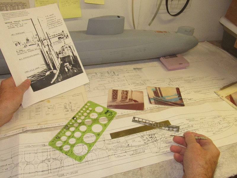
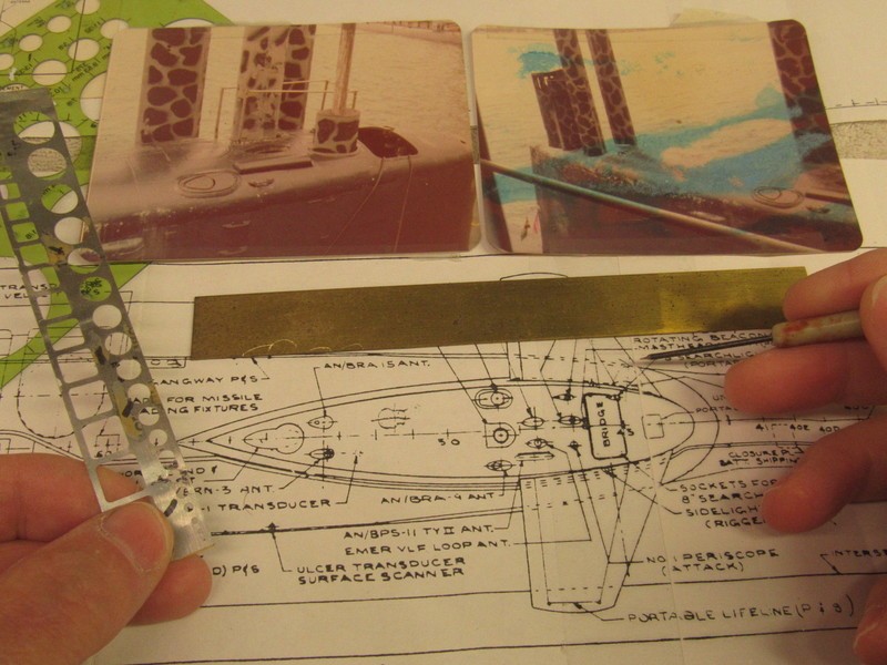
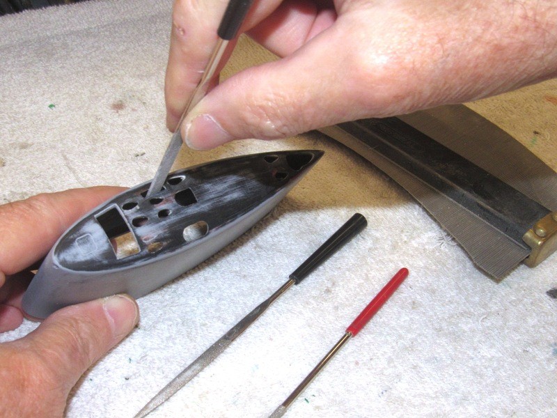
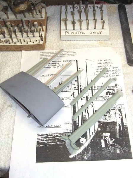
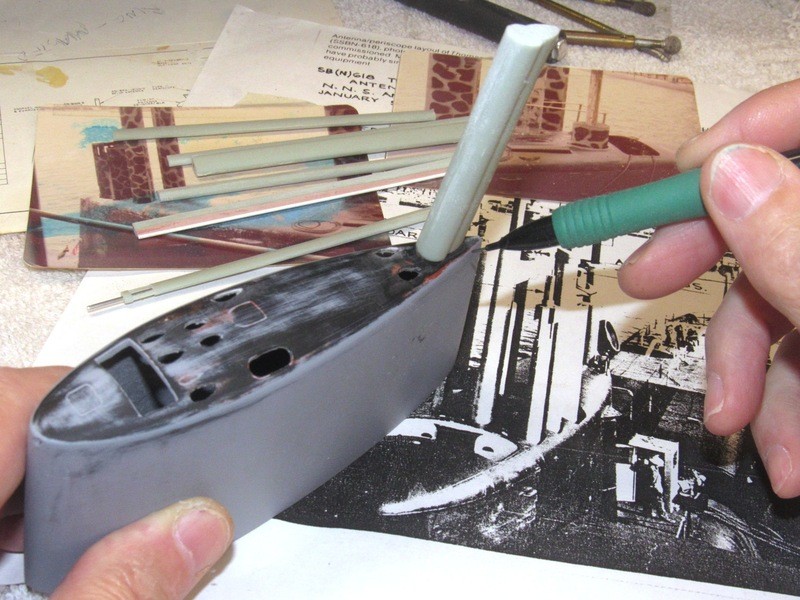
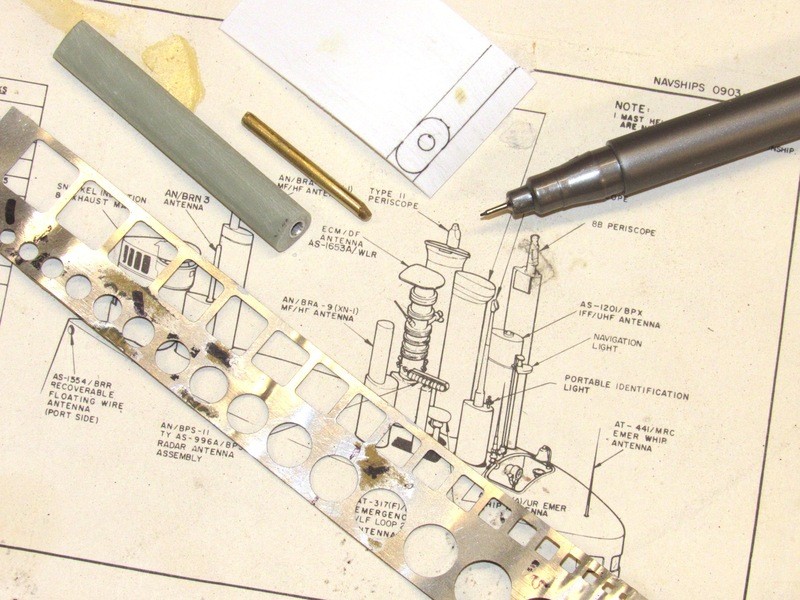
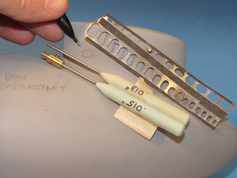
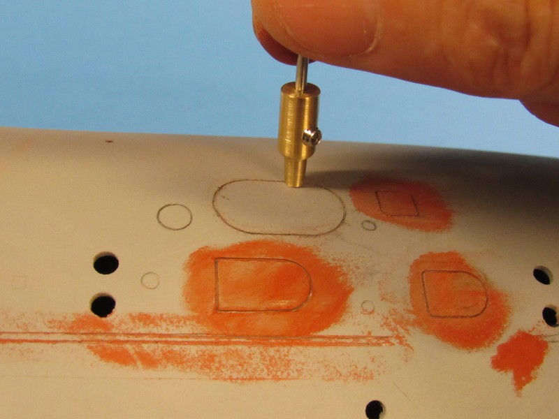
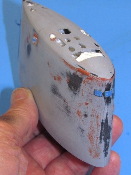
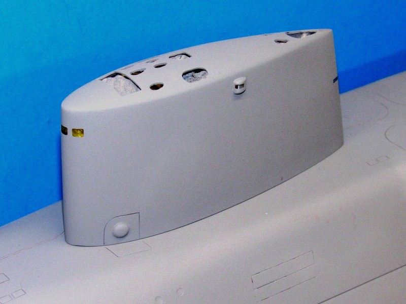
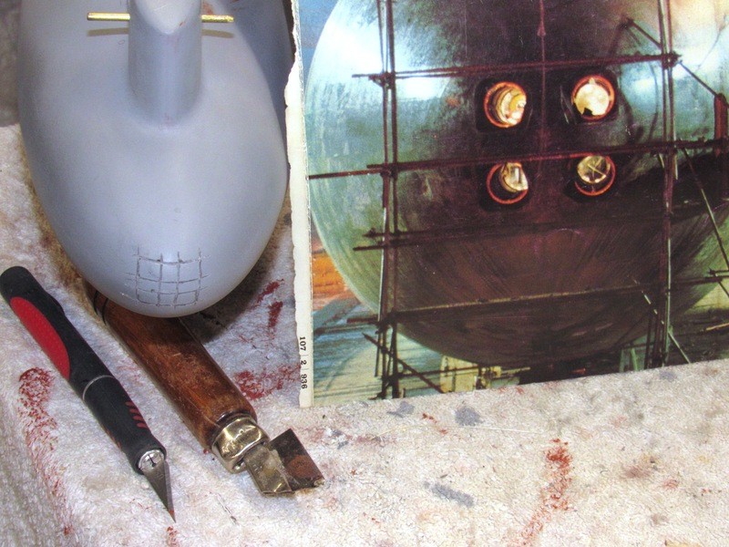
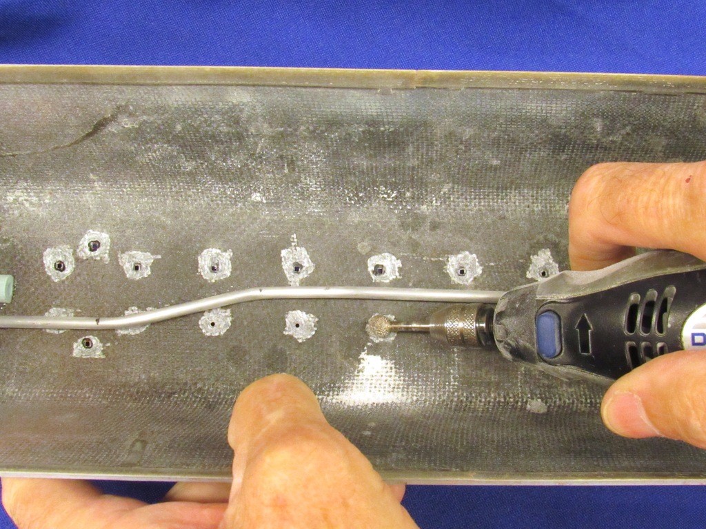
First task was to identify where the deadlights would go at the upper leading edge of the sail, mark their outlines with pencil – a bit bigger than they will eventually be – and cut open the three opening, ‘frames’ if you will, that would be back-filled with clear epoxy glue. Note just some of the reference photos used to guide me as I opened up the deadlight frames. The job entailed not only grinding the three openings, but also grinding away excess laminating resin from within the sail. It would not do to have clear deadlights only to let them reveal a way out of scale thickness to the deadlight framing.
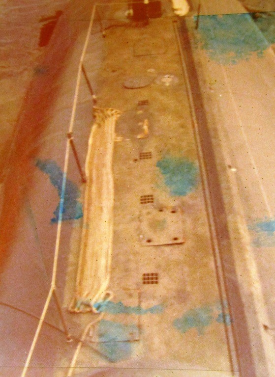
(The color photo is our stop-over at Oahu before completing our transit to New London for Poseidon conversion. My ninth and last patrol on the Pig-Fish. Spent the rest of my career in the diving community; ships husbandry, salvage, security swims, training, and chasing Filipino gal’s around bar-stools).
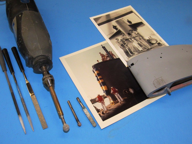
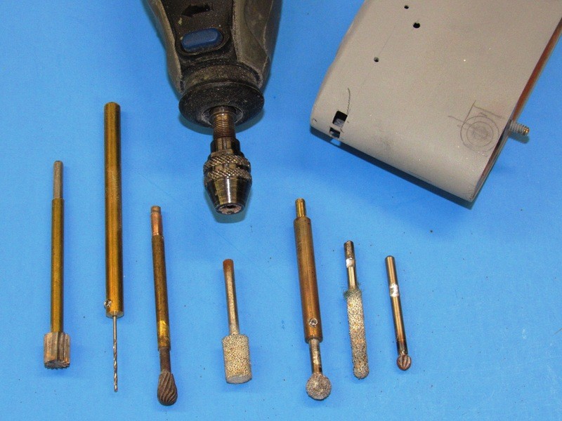
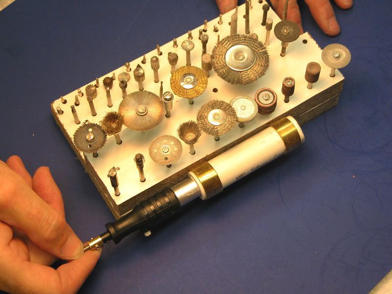
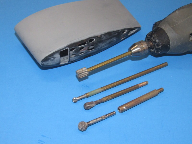
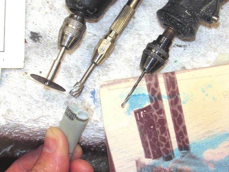
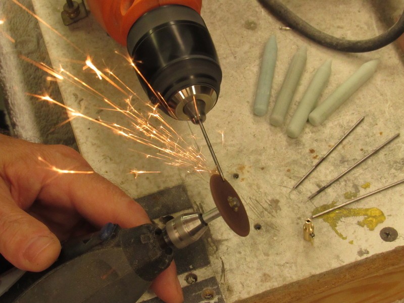
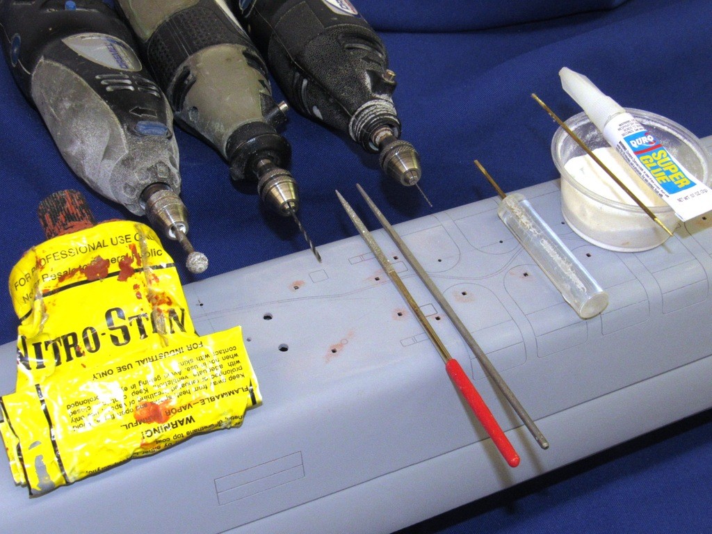
I’ve developed shank-extensions for my Dremel moto-tools. The objective of that accessory is to increase the reach of a rotary tool much farther from the chuck than the typical tools shank length of two-inches will permit.
The shank-extensions are turned from 3/16” diameter machine-brass that is reduced to the 1/8” diameter at the chuck end to fit the moto-tool, and bored .128” at the tool end to accommodate the 1/8”shank of the typical Dremel rotary tool. Note that tools to be used with the shank-extension have a flat ground in, this to fit a set-screw that keeps the cutting tool from rotating in the shank-extension when serious torque is applied.
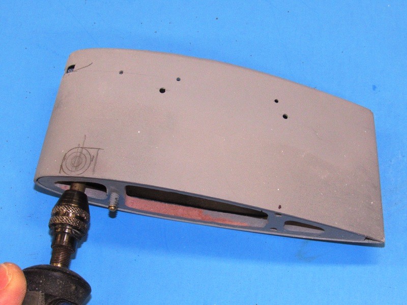
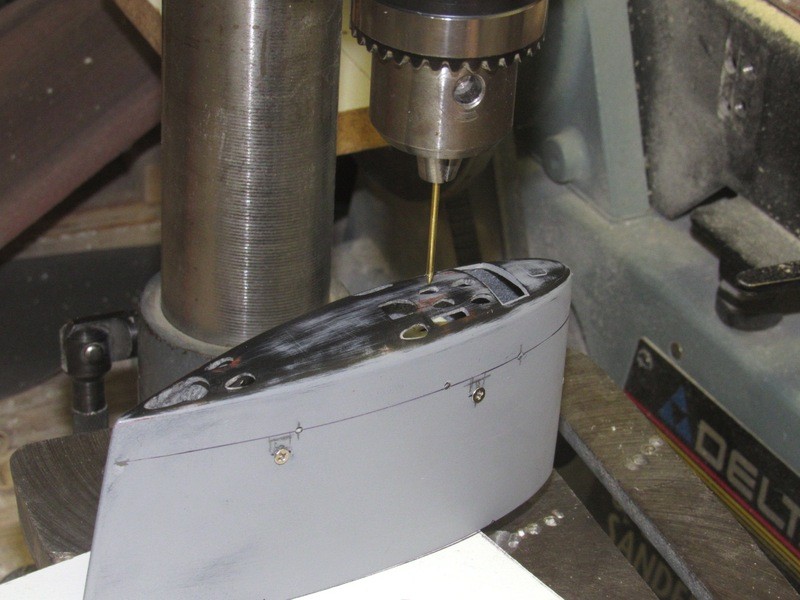
Using the shank-extension to get the rotary burr up and behind the deadlight openings, thinning the frames to a more scale like thickness.
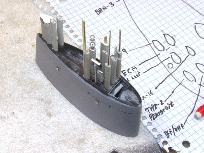
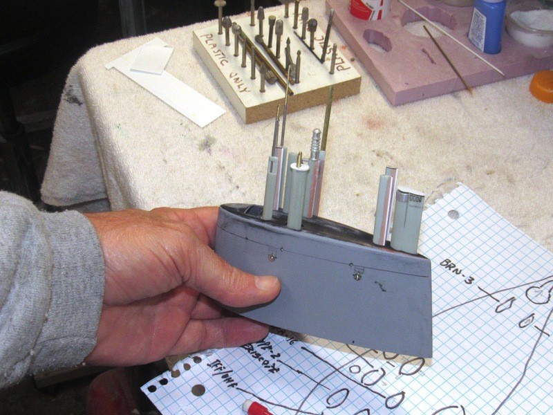
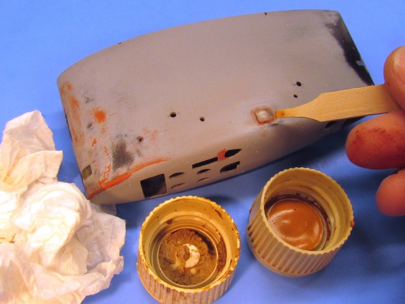
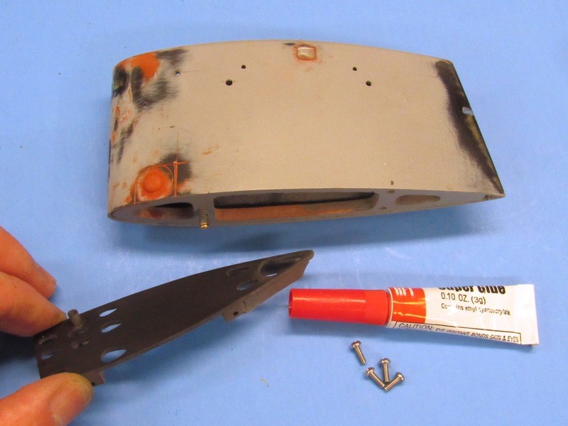
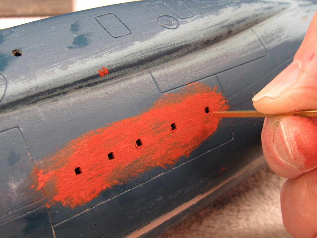
Those holes in the sides of the sail will soon go away. They are for alignment and temporary fixture of the internal mast foundation piece – made removable to facilitate establishment of the registration between top-of-sail mast openings, and the openings in the mast foundation. That work done I’ll glue the foundation within the sail permanently, fill the holes, and proceed with another coat of primer to the sail, but only after I’ve masked off the deadlights, emergency stern light lens, and two running light lenses with little strips of masking tape.
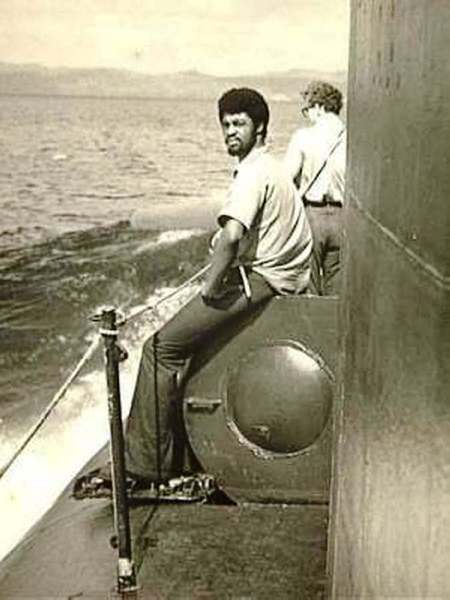
The door outline on the port side of the sail denotes where we got access to the control room and bridge from topside. A RenShape hemispherical ‘bulge’ would be added to the port base of the sail and around it the outline of the door fairing would be scribed in.
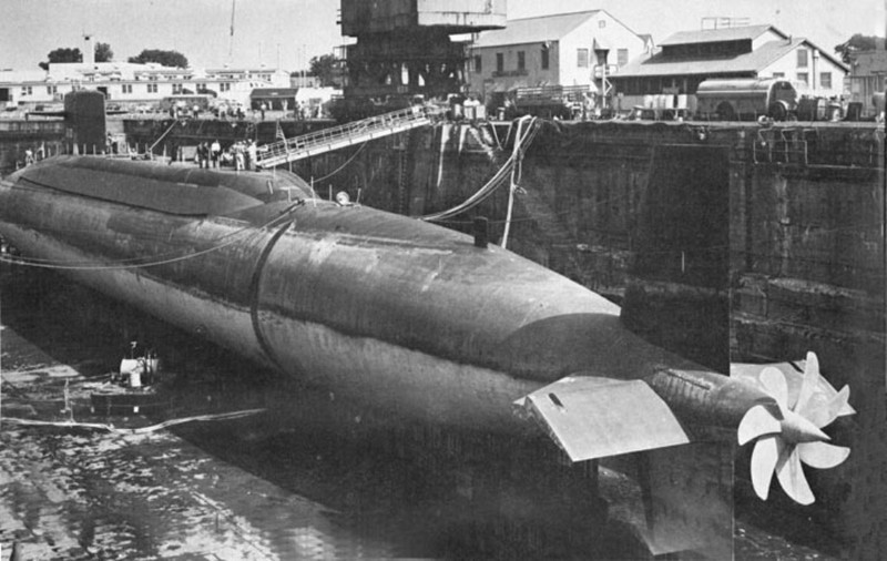
You can just make out the WEBSTER’s unique bow planes in the background of this shot. As the guys in this picture are in dungarees I assume this shot was taken as these guys were either underway on a pre-patrol shake-down or swapping piers at Apra Harbor.
The David Manley method of representing practical clear deadlights is to open up the frames, back the front end of the sail with tape (the clear packing tape you see to the extreme right of the shot), and from the inside of the sail apply some catalyzed clear epoxy, laid on as two or three coats, permitting each to cure hard before laying down the next. You leave it to capillary action to draw the glue into the edges of the frames and over the backing tape.

The tan masking tape was used to make a two-layer thick strip of tape, pieces cut and used to build up a raised edge around the deadlight openings – this producing a void above the surface of the sails leading edge that would accommodate the epoxy, insuring that there will be epoxy to shave away, not add, when it came time to abrade the clear epoxy deadlights into conformity to the surface of the sails leading edge. Well … that was the plan, anyway!
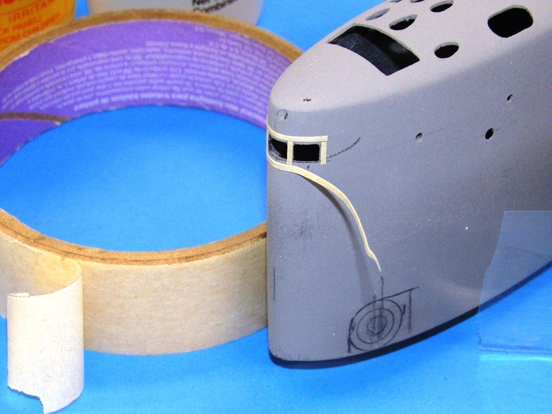
Over the stand-off masking tape strips and leading edge of the sail was placed a piece of clear packing tape – this being the means of giving rough form to the outside surfaces of the eventual epoxy resin deadlight lenses.
15-minute epoxy glue was mixed up, applied within the sail and shoved around with a little stick to get it to fill all the deadlight openings. The sail was then set atop my vacuum table, leading edge down, and subjected to a hard vacuum for ten-minutes. The hope was that the expanded entrapped bubbles within the glue (a consequence of mixing and exothermic reaction frothing) would expand, pop at the surface of the glue, and the gas evacuated. That was my hope. (The same process applied successfully all these years to resin tool making and some forms of resin casting).
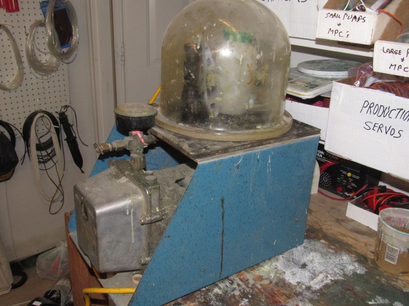
The vacuum tables bell-jar removed you get a closer look at the little puddle of cured epoxy glue that gave form to the clear lenses of the three sail deadlights.

After the epoxy glue cured as hard as it was going to get I removed the big piece of clear packing tape from around the leading edge of the sail and then pulled off the masking tape strips used to put the outside face of the raw deadlight lenses a short distance off the face of the sails leading edge. And this is what I got.

And now … let’s back light this thing: WHAT A MISERABLE JOB!!!! Just look at all the little bubbles captured in the epoxy glue deadlight lenses. God Damit!
Clearly, pulling a vacuum on the glue before it changed state from liquid to solid did not de-air the mix any at all. It must be the thickness of the glue: even though the vacuum increased the size, and hence the buoyancy, of the entrapped gas, the viscosity of the glue overcame the buoyant force of the enlarged bubbles that would have pushed them upward to the surface, breaking, and giving up the entrapped gas to the vacuum.
Here’s what I think happened: As I only had ten-minutes to hold vacuum it clearly was not long enough to get those bubbles to migrate from mix to surface. The obvious fix is to use a thinner formula adhesive – one where the bubbles can travel the required distance in the given time. And/or use an epoxy of much longer pot-life. I’ll kick this thing. Maybe the next project will benefit from these findings?
I’m going with this as is, tiny bubbles and all. One must, from time to time, be pragmatic and accept things as they are and move on. Otherwise projects never get completed. You rivet-counters, procrastinators, and project quitters know exactly what I’m talk’n bout!
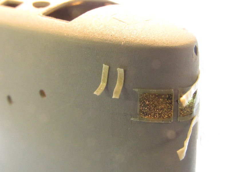
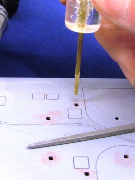
Even though I took the precautionary measure of building up the epoxy deadlight lenses a bit proud of the sails leading edge surface I still failed to completely build a height of epoxy tall enough to avoid a few divots, like those you see in the center deadlight lens. This was fixed by a few drops of epoxy glue applied to each divot and, once that had cured hard, filing the repaired areas flush.
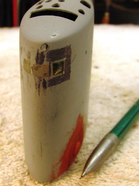
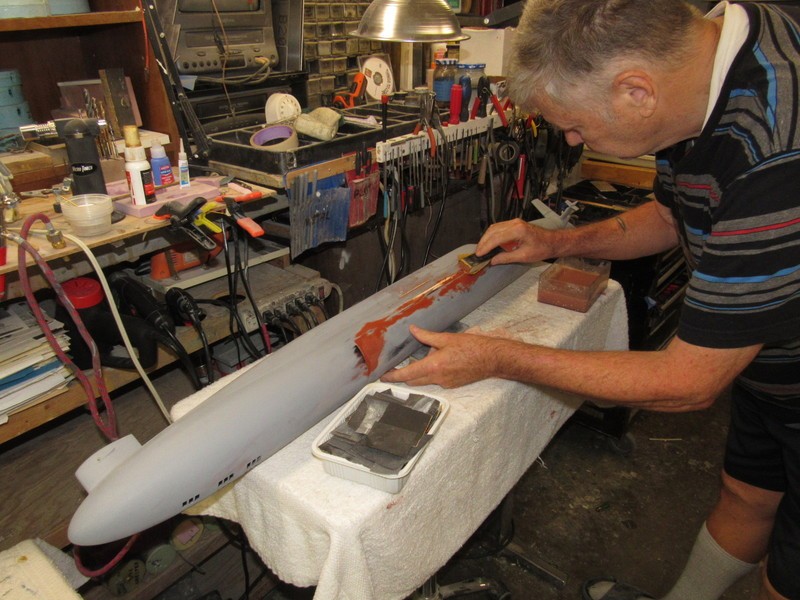
To guide me – keeping the file from digging into adjacent work as I took the lenses down to conform to the sails leading edge – I marked around the epoxy areas with a pencil. When the file got the lens almost even with the surrounding sail structure I would observe the start of file-marks on the penciled areas, telling me to stop with the filing and continue the work carefully with descending cuts of sandpaper backed up with a sanding block.


























































» RC Drift Gyro for pitch control
» WW2 mini sub build
» sonar data link
» Robbe Seawolf V2
» ExpressLRS - 868/915 Mhz equipment
» Flight controllers as sub levelers
» 868/915 Mhz as a viable frequency for submarines.
» Microgyro pitch controller corrosion