The Association of Model Submariners.

Would you like to react to this message? Create an account in a few clicks or log in to continue.

* THE FORUM FOR ALL THOSE INTERESTED IN BUILDING AND OPERATING MODEL SUBMARINES *


Pressure tank ballast system - ballast tank 14212712

Just a reminder that this Forum will close for posts next November (2025) . It will continue to be available as a reference on the Wayback Machine https://web.archive.org/

Pressure tank ballast system - ballast tank 14212712

For a guide to past events see the "Shows and Events" section.
B i
::::

S

P~~~

$$$

Who is online?

In total there are 24 users online :: 0 Registered, 0 Hidden and 24 Guests :: 1 Bot

None


Most users ever online was 180 on Tue Nov 05, 2019 6:03 am

Latest topics

» Futaba -868/915mhz equipment
Pressure tank ballast system - ballast tank EmptyTue Oct 29, 2024 4:46 pm by tsenecal

» RC Drift Gyro for pitch control
Pressure tank ballast system - ballast tank EmptySun Oct 20, 2024 2:04 pm by geofrancis

» WW2 mini sub build
Pressure tank ballast system - ballast tank EmptyThu Oct 17, 2024 2:34 pm by geofrancis

» sonar data link
Pressure tank ballast system - ballast tank EmptyMon Oct 14, 2024 4:31 pm by geofrancis

» Robbe Seawolf V2
Pressure tank ballast system - ballast tank EmptySat Oct 12, 2024 3:52 pm by geofrancis

» ExpressLRS - 868/915 Mhz equipment
Pressure tank ballast system - ballast tank EmptyFri Oct 11, 2024 8:58 pm by Marylandradiosailor

» Flight controllers as sub levelers
Pressure tank ballast system - ballast tank EmptyFri Oct 11, 2024 8:14 pm by geofrancis

» 868/915 Mhz as a viable frequency for submarines.
Pressure tank ballast system - ballast tank EmptyThu Oct 10, 2024 3:21 am by tsenecal

» Microgyro pitch controller corrosion
Pressure tank ballast system - ballast tank EmptyWed Oct 02, 2024 11:32 am by geofrancis

Statistics

Our users have posted a total of 12534 messages in 1992 subjects

We have 1021 registered users

The newest registered user is Mike Echo

4 posters

    Pressure tank ballast system - ballast tank

    david f
    david f
    AMS Treasurer


    Posts : 2412
    Join date : 2010-11-10
    Age : 74
    Location : Cumbria

    Pressure tank ballast system - ballast tank Empty Pressure tank ballast system - ballast tank

    Post  david f Thu Oct 02, 2014 9:09 am

    David (dgp) asked this question and I realise that this has not been discussed much on the Forum so I will see what contributions we get on this thread.

    The pressure tank system is good, in my opinion, but a weakness is operating at pressures of up to 300kPa so you need some sort of pressure vessel.

    To illustrate the scale of the problem, I see that Sheerline now use rather nice stainless steel tanks. (I understand from Nigel that they did have problems with their earlier plastic tanks??)

    So how do we go about designing and building these tanks?

    It is almost bound to be a cylindrical tank. For stability reasons to avoid the "sloshing" problem when half full keep the tank length to a minimum. Also to avoid the "sloshing" problem consider putting baffles in the tank. (Cut plastic disks to size and position them vertically in the tank spaced a cm or so apart. Don't worry about holes etc. Unless you are an expert disk cutter they will leak enough anyway! (Don't glue them.)

    If you are finding the idea of a pressure tank rather daunting a quick search of the internet shows that ordinary plastic (pvc) pipe of about 3 to 4 inches in diameter has a working pressure of about 1000 kPa. Even a humble plastic soft drink bottle has a working pressure of about 300 kPa so you could use this for pump trials etc.

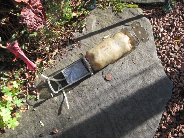
    With the tanks I made I decided to adopt a belt and braces approach by cladding the pvc pipe with about a 1/4 inch of glass fibre. I haven't had one split or leak yet!
    Pressure tank ballast system - ballast tank Img_4210

    The photo shows an early tank which I dragged out of the shed to photograph this morning (Nice morning up here!) This one used the bases of 2 plastic soft drink bottles as the former for the fibreglass. (I should explain that I am using not using the pressure tank system much nowadays because I have moved onto piston tanks.)

    avatar
    dgp1957
    AMS member


    Posts : 42
    Join date : 2012-12-30

    Pressure tank ballast system - ballast tank Empty Re: Pressure tank ballast system - ballast tank

    Post  dgp1957 Thu Oct 02, 2014 11:53 am

    Thanks David, I am thinking of using the middle section of my cylinder as ballast tank, if I epoxy two 3mm acrylic disks to each end then reinforce the cylinder with FG and resin should that result in a strong enough vessel?

    David
    david f
    david f
    AMS Treasurer


    Posts : 2412
    Join date : 2010-11-10
    Age : 74
    Location : Cumbria

    Pressure tank ballast system - ballast tank Empty Re: Pressure tank ballast system - ballast tank

    Post  david f Fri Oct 03, 2014 6:06 pm

    I think I would be wary of using different plastic from the tube for the end caps. Maybe best to stick close to plumbing fittings and adhesives - they are well tested in plumbing systems.

    The photo of the tank shows that the tank is slipped inside the WTC on a sort of " Tech Rack". I am not quite clear how you intend to do it but this has the virtue of being able to move the position of the ballast tank easily.

    I would also cover the whole thing in glass fibre. The flat end caps will "bow " with pressure.

    In one tank I put a stainless steel theaded rod through the tank before covering the tank with GRP. This provided  support for the end caps ( a bit like a boiler stay.) and also meant that I could fix the internal baffles on it.

    I am not a pressure tank designer but these tanks have worked fine for me over the years using the red pumps. (I worry slightly that the lapped brass impeller pumps may produce a higher pressure. It would be nice if someone could actually test them?! I have the figures for the red pumps somewhere.)

    David


    Last edited by david f on Fri Oct 17, 2014 3:45 pm; edited 1 time in total
    david f
    david f
    AMS Treasurer


    Posts : 2412
    Join date : 2010-11-10
    Age : 74
    Location : Cumbria

    Pressure tank ballast system - ballast tank Empty Re: Pressure tank ballast system - ballast tank

    Post  david f Fri Oct 17, 2014 3:31 pm

    I've found and attached some extracts from my original construction logs to throw some more light on pressure tanks and maybe help someone experimenting with this at the moment. (Sorry about the mixture of units but US readers may feel at home!)

    The conclusions from these notes are that the original red pumps could give a maximum pressure of about 160kPa. They needed 12volts not 6volts. My ballast tank took 530g of water. The fibreglass sheathed vessels could stand at least 350kPa. I don't seem to have made any note of filling time but they would pump 530g of ballast in less than 1 minute. (And I did go for a standard WTC.)

    If anyone could carry out similar trials on the Kavan pump suggested by Swipe on here recently, you would do us all a favour.

    Swipe's pump details follow:
    "Kavan produce a pump with lapped brass gears. At about £20 It's a little more pricey than a cheapy from Halfords etc. also it's a bit bigger than some pumps, but it has pretty decent pumping speed and should reward you with good service.

    http://www.sussex-model-centre.co.uk/shopexd.asp?id=1283"


    1 August, 1999
    TEST OF RED SCREEN WASH PUMP ON 12v
    (12 v unit made by SEILL, France.)

    Needed to try sealed ballast system.
    On 6v with vent open gave 300 g of water to fill completely. i.e. tank capacity.
    What proportion is 300 g of total displacement? Need to weigh the sub.

    6v sealed vent. Only put 100 g in – no good.

    12v sealed vent . Got up to 200g but container leaked at seam. Not very good construction!

    3 August, 1999

    Repaired dive tank and tried pump test again. This time got 200g in with pump on 12v, but cylinder still leaks slightly.

    Therefore pump gives 2 bars pressure.

    14 August 2000
    Pressure gauge trials. (Reads 6 bars.)
    Screenwash pump gives 1.6 bars.
    GRP vessel tested to 3.5 bars. (Silicone rubber connections not too good at this pressure. That yellow Tygon is better.)

    September 2010

    IDEA FOR STANDARD RADIO & BALLAST SECTION:
    Charlie and R7 use a pressure tank with a maximum water input of 530g (with new pump) and the centre of this tank is situated 14” from stern bulkhead.  Overall length of this compartment for Charlie class is 22”.
    So there would be a lot in common between the 3 subs.
    So common pressure or piston tanks for all 3 models?


    Last edited by david f on Fri Oct 17, 2014 3:48 pm; edited 1 time in total
    david f
    david f
    AMS Treasurer


    Posts : 2412
    Join date : 2010-11-10
    Age : 74
    Location : Cumbria

    Pressure tank ballast system - ballast tank Empty Re: Pressure tank ballast system - ballast tank

    Post  david f Fri Oct 17, 2014 3:37 pm

    I've just copied this thread from David (dgp) across to keep information on pressure tanks together:

    Need a re-think I had a bit of a disaster trying to add fibre glass to re-inforce my cylinder, resin wouldnt stick to it, thinking about using threaded rod to secure the ends to the cylinder, is that a viable option? Regarding pump, if I use a water pump to fill cylinder with water then do I need to reverse the pump to empty the tank or will air pressure in tank do the job for me? if so how could I avoid water emptying from tank when pump stopped, is that what pinch valve/solenoid valve would do?

    Mystified
    David

    Hi David,

    It sounds like you have hit a steep part of the learning curve!

    If it is any consolation you have identified the major problem in the pressure tank ballast system - making a suitable tank! Lot's of people giving advice out there but very few people have actually done it.

    My advice needs to be given with the background that I have made about 3 of these tanks and they have all worked well. Mind you I now have moved onto home made piston tanks using proportional control. (I am assembling my third one.) so you can perhaps see my preferred ballast system. (I know that Nigel for one does not like the pressure tank system.)

    Health warning over. Resin does not really need to stick to the plastic inner tank - you are sheathing it with a reinforcing layer of fibreglass. Cut the glass matt roughly to size and stipple it with resin. Apply to the inner tank and stipple it down with a roller or stiff brush (avoid air bubbles). You can repeat the process several times but don't leave too many days between coats to make sure that you get adherence.

    As I said earlier the plastic pipe can stand the sort of pressures we use - the problem is with the design of the end caps. Maybe this technology could move on by using stainless steel tanks like Sheerline. Could anyone out there oblige by making tanks, I wonder? Or perhaps buy them from Sheerline.

    The basic system does not need a reversible pump. The air bubble pushes the water out through the pinch valve. However I prefer to use a reversible pump and I use an electronic switcher. The reason for this is that you can "lose your bubble" after some minutes and hours. The reversible pump helps to get the water out.

    Sorry you are having these problems and let us know how you get on. It is good to see someone who is doing rather than just talking about it and mystification can be part of the process!

    David
    John Wrennall
    John Wrennall
    AMS member


    Posts : 157
    Join date : 2011-11-16
    Age : 78
    Location : Leyland

    Pressure tank ballast system - ballast tank Empty Re: Pressure tank ballast system - ballast tank

    Post  John Wrennall Fri Oct 17, 2014 8:39 pm

    Hi all.

    There is an alternative to fibre-glassing the tank ends.

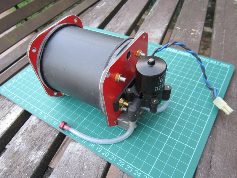
    I make up spigotted end caps and rubber seals and hold the lot together with

    good old fashioned nuts and bolts.

    Pressure tank ballast system - ballast tank 1710
    (see Abyss Explorer build log for component photos)

    The red plates are aluminium/plastic sandwich to spread the loading,
    The 4 thru bolts are all sealed with o rings. pump is reversible

    Another thought on pressure tanks, If you only need say 250cc of water to dive then the pressure increase in a 1000cc tank will only be half that in a 500cc tank - Quarter full as opposed to half full.
    (Remember Boyle's Law from school    P1*V1 = P2*V2 )

    Don't forget your anti-surge tank baffles.

    John
    david f
    david f
    AMS Treasurer


    Posts : 2412
    Join date : 2010-11-10
    Age : 74
    Location : Cumbria

    Pressure tank ballast system - ballast tank Empty Re: Pressure tank ballast system - ballast tank

    Post  david f Sat Oct 18, 2014 8:36 am

    Very nice, John. Thanks for sharing this.
    Really clear description of an alternative pressure tank design.
    avatar
    Kevin D


    Posts : 129
    Join date : 2014-04-24
    Age : 62
    Location : Norwich

    Pressure tank ballast system - ballast tank Empty Re: Pressure tank ballast system - ballast tank

    Post  Kevin D Fri Feb 20, 2015 8:07 pm

    John Wrennall wrote:Hi all.

    There is an alternative to fibre-glassing the tank ends.

    I make up spigotted end caps and rubber seals and hold the lot together with

    good old fashioned nuts and bolts.

    Pressure tank ballast system - ballast tank 1710
    (see Abyss Explorer build log for component photos)

    The red plates are aluminium/plastic sandwich to spread the loading,
    The 4 thru bolts are all sealed with o rings. pump is reversible

    Another thought on pressure tanks, If you only need say 250cc of water to dive then the pressure increase in a 1000cc tank will only be half that in a 500cc tank - Quarter full as opposed to half full.
    (Remember Boyle's Law from school    P1*V1 = P2*V2 )


    Don't forget your anti-surge tank baffles.

    John


    Hi John

    I really like the look of your pressure tank, an excellent looking design. I have a few questions that I hope you won't mind answering.

    What is the capacity of the tank in the picture?

    The tie rod o rings are they sandwiched between the end cap and Aluminium clad plastic end plate?

    What is the value of the capacitor used for suppression of the pump?

    How many baffles were fitted?

    Phew!!! I think that's everything.

    Kevin


    John Wrennall
    John Wrennall
    AMS member


    Posts : 157
    Join date : 2011-11-16
    Age : 78
    Location : Leyland

    Pressure tank ballast system - ballast tank Empty Ballast tank spec

    Post  John Wrennall Sat Feb 21, 2015 2:36 pm

    Hi there Kevin.

    Thanks for the tank inquiry, the details are as follows:

    The pipe used was plastic, 75mm ID and about 100mm long which gives a total capacity of just under half a litre (440cc) Of course with this being a sealed tank not all this volume is available for water so lets say half is water. This represents a ballast weight of 220 gm (nominally 7 ounces)
    This is more than enough with the other lead weights to take the boat down. If you look closely, you can see one of these attached to the tank.
    The pump is the normal windscreen washer pump purchased from AFL (my local motor factors shop)
    and has been plumbed in WITHOUT any valves which gives additional fail safe surfacing as the compressed air forces the water back through the pump gears. Depth keeping suffers though and I intend to fit a valve on the next maintenance strip down.

    Sealing of the tank is via a rubber annulus ring at each end of the tank and the through-bolt holes in the end caps are countersunk slightly on the outside to take a small O ring (8 in all) which are compressed by the ' load spreading plates' . The tank has only the one baffle, any longer and I would have fitted two.

    The pump was fitted with a single capacitor from a MFA motor suppression kit, can't remember the exact value. Screws holding the pump are countersunk on the red end plate and do NOT go through the tank. An Electronizer switcher was used to drive the pump as I could not get an Action switcher to work correctly in situ despite it working OK on the bench...(How many times have we heard that before?)   will probably try a small ESC next time


    In case you were wondering, the extra large hole in the red end plate was drilled in anticipation of a possible conversion to a vented tank but was not needed.

    With regards to your other query about the Valve I sent you, sorry but I'm down to my last one, already coupled to an air pump and earmarked for a type 9.

    The penultimate valve was given away about a fortnight ago with instructions to return it if his project didn't work - parts he's using include 4 channel TX/RX, servos, airbrush compressor, valve  and a TRUMPET  and he calls me MAD !!!!!


    John
    avatar
    Kevin D


    Posts : 129
    Join date : 2014-04-24
    Age : 62
    Location : Norwich

    Pressure tank ballast system - ballast tank Empty Re: Pressure tank ballast system - ballast tank

    Post  Kevin D Sat Feb 21, 2015 4:01 pm

    Hi John,

    Thanks for the details, your tank really caught my eye because I actually have all the materials you used already in my workshop, even the pump and Aluminium clad plastic in RED!!!

    The large hole did have me thinking for a while but I eventually worked out that it wasn't being used.

    No worries about the valve I just thought I would ask in case you had one available. I'm intrigued to know what is occurring with that parts list, especially the trumpet.

    Kevin

      Current date/time is Thu Nov 21, 2024 11:21 am