The Association of Model Submariners.

Would you like to react to this message? Create an account in a few clicks or log in to continue.

* THE FORUM FOR ALL THOSE INTERESTED IN BUILDING AND OPERATING MODEL SUBMARINES *


Join the AMS - Registered Forum users can become members of the AMS and it's free ...... To join send an email with your name , address and phone number to amstreasure@googlemail.com


For a guide to past events see the "Shows and Events" section.
Bournville MBC on Sunday 11th August 2024, 10.00 i
::::

Papplewick Pumping Station Sub Weekend, 14th & !5th Sept 2024

P~~~

$$$

Who is online?

In total there are 2 users online :: 0 Registered, 0 Hidden and 2 Guests :: 1 Bot

None


Most users ever online was 180 on Tue Nov 05, 2019 6:03 am

Latest topics

» Futaba -868/915mhz equipment
Akula 1/144 scratch build EmptyYesterday at 4:46 pm by tsenecal

» RC Drift Gyro for pitch control
Akula 1/144 scratch build EmptySun Oct 20, 2024 2:04 pm by geofrancis

» WW2 mini sub build
Akula 1/144 scratch build EmptyThu Oct 17, 2024 2:34 pm by geofrancis

» sonar data link
Akula 1/144 scratch build EmptyMon Oct 14, 2024 4:31 pm by geofrancis

» Robbe Seawolf V2
Akula 1/144 scratch build EmptySat Oct 12, 2024 3:52 pm by geofrancis

» ExpressLRS - 868/915 Mhz equipment
Akula 1/144 scratch build EmptyFri Oct 11, 2024 8:58 pm by Marylandradiosailor

» Flight controllers as sub levelers
Akula 1/144 scratch build EmptyFri Oct 11, 2024 8:14 pm by geofrancis

» 868/915 Mhz as a viable frequency for submarines.
Akula 1/144 scratch build EmptyThu Oct 10, 2024 3:21 am by tsenecal

» Microgyro pitch controller corrosion
Akula 1/144 scratch build EmptyWed Oct 02, 2024 11:32 am by geofrancis

Statistics

Our users have posted a total of 12534 messages in 1992 subjects

We have 1020 registered users

The newest registered user is JSAF

+6
John Wrennall
merriman
david f
Dr.Schmidt
bwi
tattooed
10 posters

    Akula 1/144 scratch build

    bwi
    bwi
    AMS member


    Posts : 81
    Join date : 2015-01-17
    Location : Belgium

    Akula 1/144 scratch build Empty Akula 1/144 scratch build

    Post  bwi Sat Jan 17, 2015 9:14 pm

    Hi gents,

    As promised in my introduction to this forum here is my building thread.

    To be honest I have one running on another forum….so why another one? Well I want to share ideas with as many people as possible. All the crafts and tricks I use for building my sub I learned through the WWW from other people. I believe I have to give something back in return for all the lessons I have learned from you guys out there.

    I will mention some people in my thread where I got ideas from, not to advertise for them or promote them, but I strongly believe in Referencing, no more no less.

    As I made already some substantial progress with the built I will divide the elapsed time into small chapters till the “as is” situ.is reached.

    I have started with my long (I have ordered the plans in 1997 from deep sea designs “Greg Sharpe”) planned scratch building project of an akula submarine almost two years ago.

    In the nineties some names were all over the web with a lot of information David Merriman was such a name. In 2006 I have stumbled upon a very interesting project of Jerome Simon. In 2010 I have purchased  Wayne Frey’s book “Russian Submarines” witch is also a great help for my built.

    As I have a family to take care of and a full time job the progress of my built will be slow but continuous, furthermore the appetite to build has to be there, for me it has to be relaxation not another stress building nerve wracking thing. No appetite no Build!!.

    The scale I have chosen in function of transportation possibilities. It had also to be hand carried with ease. So the easiest for me was to shrink the “deep sea designs plans” (1/96) 1,5 times, so scale 144 was the outcome. The sub would measure 800mm what was acceptable for me. The scale was set next the making off the hull.

    As previous stated I have read the thread of Jerome Simon building his akula and this made my decision easy. I made a master, made a mold from the master and finally layed-up the hull in the mold.

    Grtz,
    Bart
    bwi
    bwi
    AMS member


    Posts : 81
    Join date : 2015-01-17
    Location : Belgium

    Akula 1/144 scratch build Empty The masters

    Post  bwi Sat Jan 17, 2015 11:16 pm

    Making the master:

    I have started out with some hard wood from the old windows of my house. First problem to tackle the dimensions of my lathe, distance between centres is only 400mm, so I decided to make the master out of 3 pieces, each piece consisted out of two halves bolted together so I could separate them after the piece was shaped on the lathe. After the three pieces were shaped the halves have been separated and glued together resulting in a top half and bottom halve master.

    The pieces were turned on the lath by hand. As a novice in wood turning I first made the pieces cylindrical and then made an recess every 10mm till I reached the correct diameter and finally removed the remaining material between two recesses. Next step was sanding the pieces, this resulted that everything was covered with a nice red carped of dust in the basement/my workshop. And as I left the door to the basement open the carped of dust continued into the living quarters of the house.

    The pictures below showing the master halves; Cleary visible are the glue seems and boltholes for holding the halves together in the lathe process. The traces of bolts in the centreline of the master are remnants of the bolts applied for the centres of the Lathe. The masters have been coated with filler.

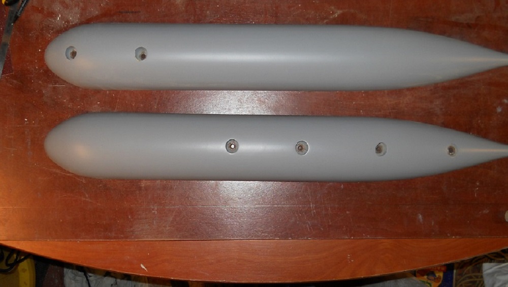
    Akula 1/144 scratch build Akula_1

    Akula 1/144 scratch build Akula_2

    This picture shows the plugs for filling the boltholes in the master (made out of a broomstick). Afterwards more sanding also the flat surface of the master halves to get an even seem between them.
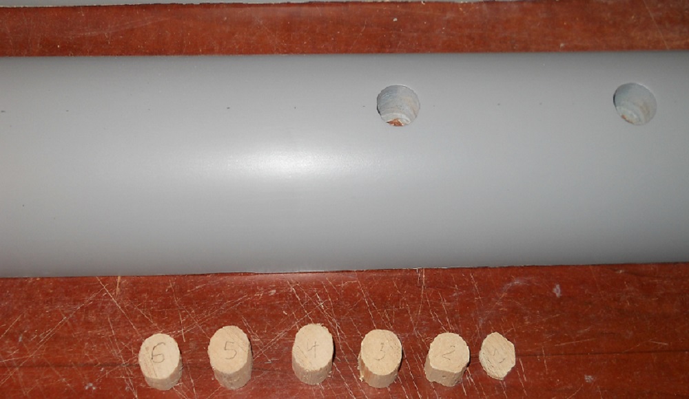
    Akula 1/144 scratch build Akula_3

    The plugs were glued in the bold holes with epoxy glue so far so good. Remaining gaps were filed with the same glue. Master halves where sanded and primer was applied.

    The flat rear deck I have constructed out of a piece of 3mm Polycarbonate sheet….sanded one end till I had a sharp edge for the rear transition with the hull. I have attached the flat deck to the hull by means of screws, one every 30mm , so it followed the radius of the hull nicely. The gaps at PS and SB side, between the hull and the flat deck, I decided to fill up after the sail was installed.

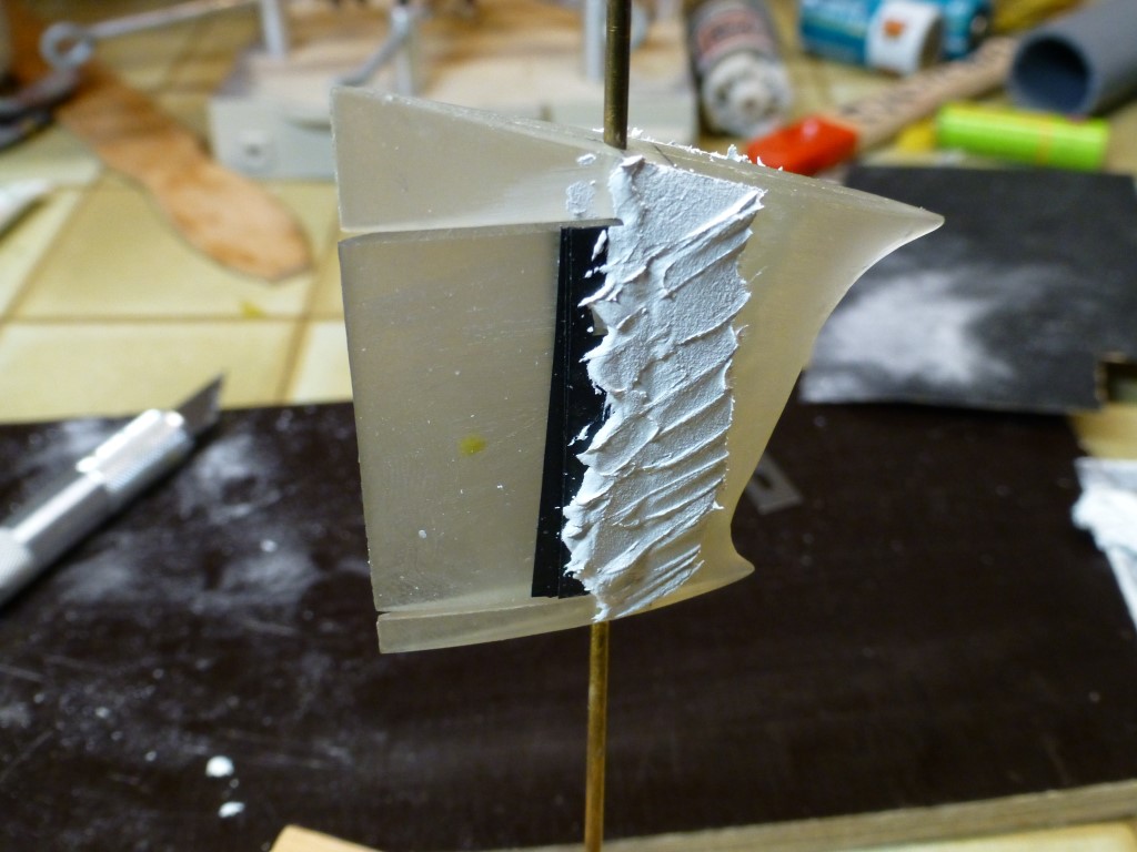
    On the sail I have cheated a little bid. A few years ago I have purchased a D**AS kit, never assembled it as it did not meet my expectations. I took the sail of the D**AS kit and used it on my present build. It was glued in place by means of epoxy glue.
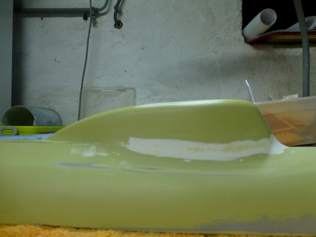
    I also used the stuff to get the curved transition between the hull and sail and hull and flat deck. I thought this would do the job…..it did till I went sanding the stuff in shape. I will keep it polite…..never again that stuff is very hard to sand and the result is poor…surface can be compared with that of the moon . I have tried to rectify it by means of filler but the attempt has crashed and burned; see picture below.

    Akula 1/144 scratch build Akula_19

    So I went to looking for another product to finish the job. I remembered “**** metal glaze” works well but this product cannot be purchased in Belgium. I found a store that has specialized in Polyester, resins & fiberglass. After I had explained what I actually wanted (easy to sand and quick drying) I went home with an equivalent of the a.m. product……applied the stuff and went sanding…..after a few second one could see a very happy man in his basement ….the stuff worked great.

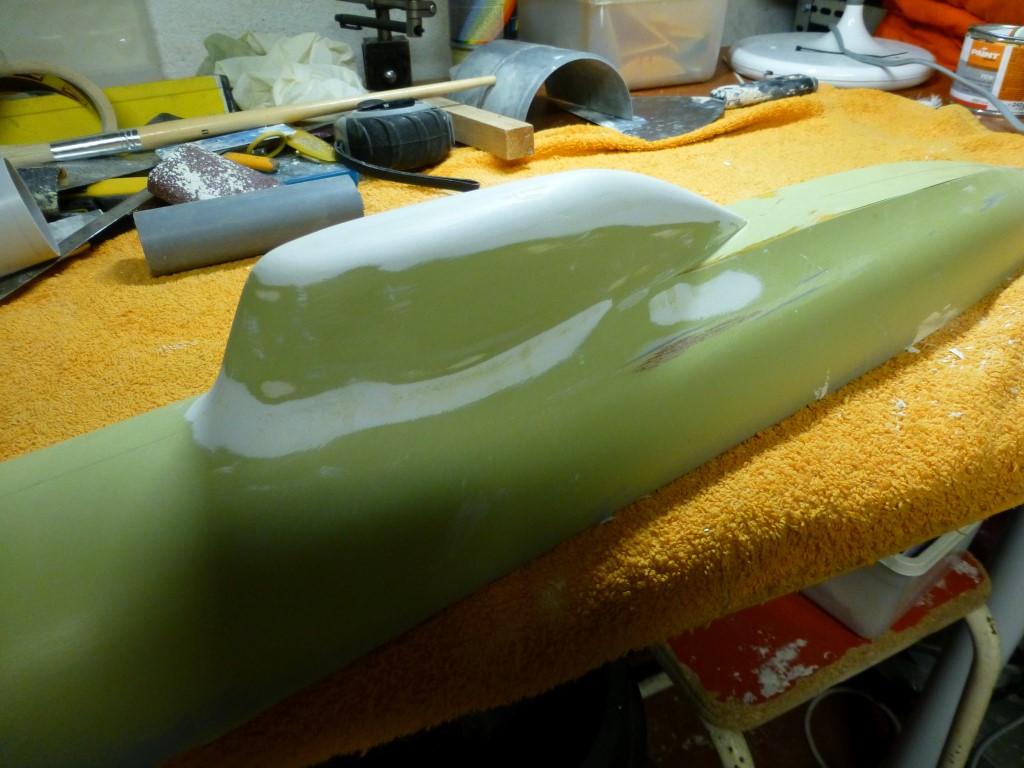
    Picture below; the white iwo the transition hull/sail is the EURIKA stuff. (still smiling as I write this dawn, I will remember the sanding of the  epoxy glue for a very long time….if it doesn’t kill you, it makes you stronger I guess.
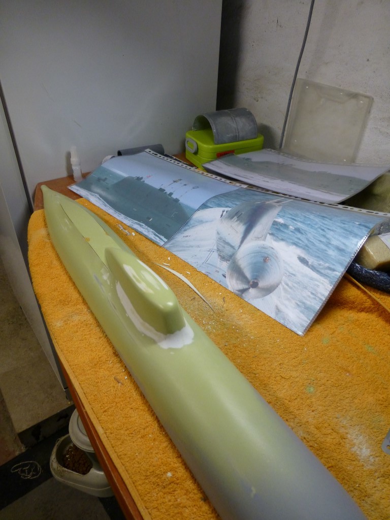
    Akula 1/144 scratch build Akula_8

    Akula 1/144 scratch build Akula_9

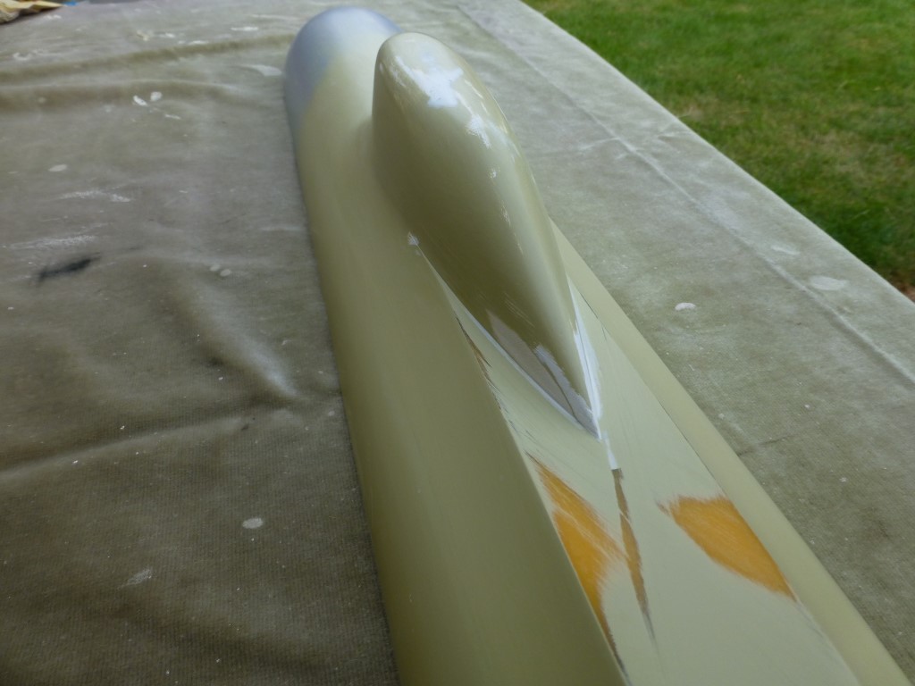
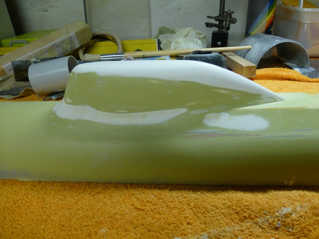
    When I was enjoying the view of my work, a bug settled in my brain. I took the drawings and noted that the sail runs horizontal for a while before it plunges towards the deck. Mine didn’t. I went through all the pictures and printed some details of the sail they only confirmed my findings. To rectify this I copied the ”as is” sail shape to a piece of 1mm [1/24”] styrene sheet. Then I copied the “to be” shape from the scaled drawing onto the same sheet. Next the difference between the two was cut out and glued onto the sail. See pictures below.
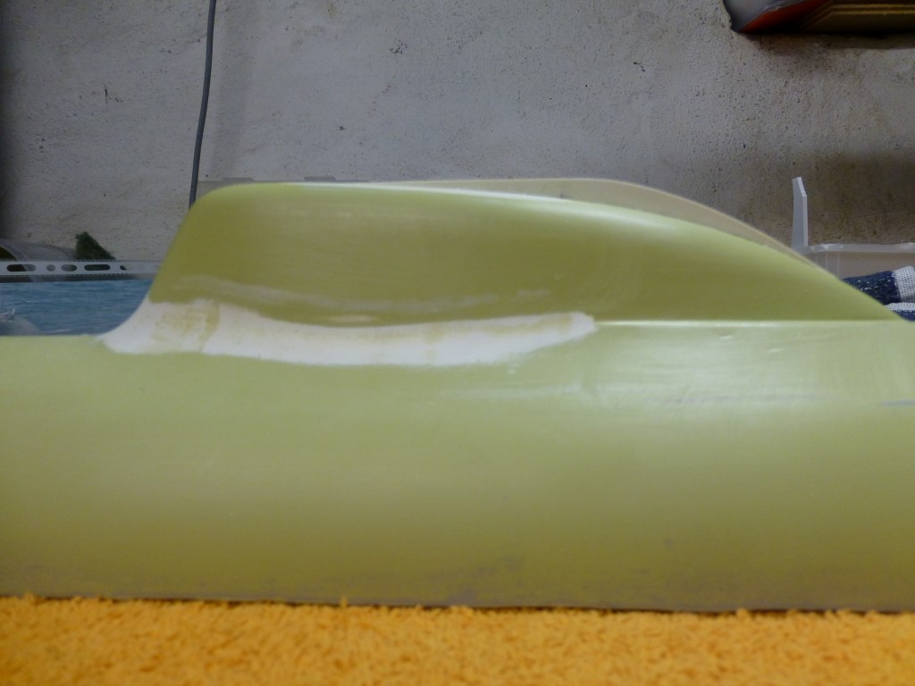
    Akula 1/144 scratch build Akula_10

    Akula 1/144 scratch build Akula_11

    The difference is small I know but visually its night and day. Then I applied the EUREKA putty to fill the gap…..in order to get the PS and SB side the same was hard but eventually it turned out fine. See below pictures; also note the sail has grown in length to. Memo to myself, next time no shortcuts!
    Akula 1/144 scratch build Akula_12

    Akula 1/144 scratch build Akula_13

    Akula 1/144 scratch build Akula_14

    Akula 1/144 scratch build Akula_15

    Outdoors. The first thing I have tackled are the bumps, gaps and scratched that showed on the master halves in the daylight, and were not revealed by the fluorescent light in the basement, using automotive spray-on putty and filler. With the temperatures at that time this stuff hardened pretty fast too.

    During this job I noted the upper and lower halve of the master didn’t pair as well as I would like, I did sand them on a flat piece of wood though. So I went to check and ascertained that the table itself was sagging slightly.

    I tried to figure out how to rectify the master halves. First I straightened out the table. A sheet of styrene on the table served as a nice smooth surface to work on. Next I applied some EUREKA putty all around the edge of the lower master halve, pressed the flat side of the master halve onto the styrene sheet and removed the excess putty that had squeezed out (and hoped it would not stick to hard)……which it didn’t, nevertheless iwo the putty I noted the styrene was affected/melted by the putty, so I was lucky.Next step I sanded the flat surface till I was happy with it.

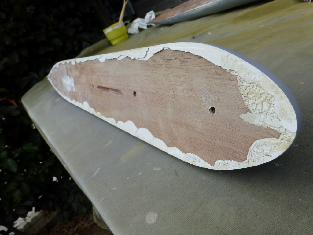
    As I did not want to try my luck a second time I tried another approach. I applied some transparent tape on the flat side of the lower halve and removed the tape that protruded from the contours of the master. Then applied some EUREKA putty all around the flat edge of the upper halve and pressed both halves together, removed the putty that had squeezed out…..and hoped I could part them after the putty dried…..which I managed.
    Picture showing the transparent tape in place on the PS, remnants of putty clearly visible.

    Akula 1/144 scratch build Akula_20

    This one showing the applied putty on the upper part.
    Akula 1/144 scratch build Akula_21

    I was very happy with the result, both halves are now mating pretty good, picture below, edges still rough but no gap.

    Akula 1/144 scratch build Akula_22

    The edges were touched up with spray putty and filler and sanded.
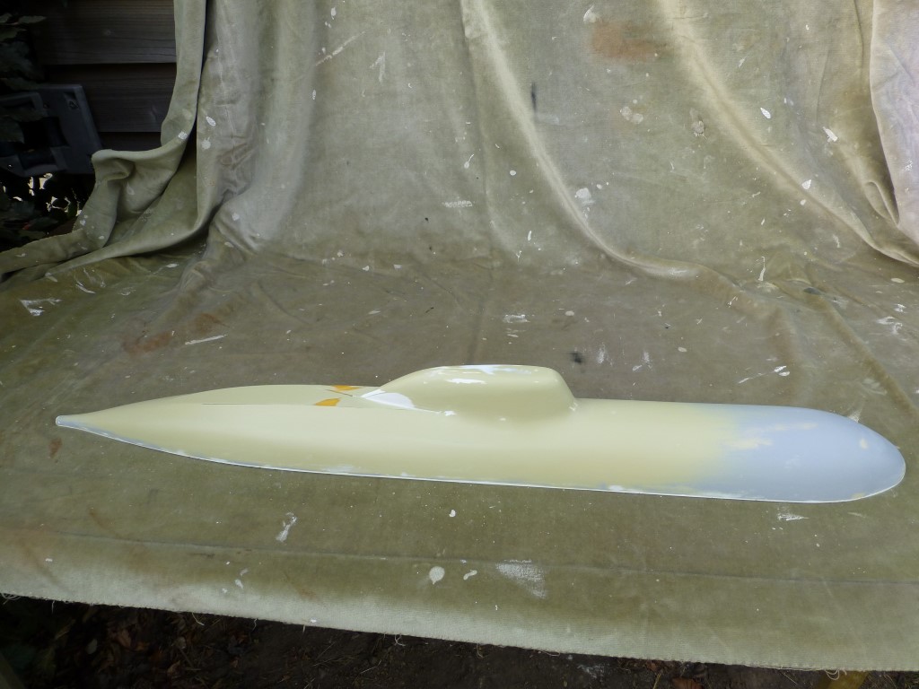
    Also I have spent a lot of time to get the trailing edge of the sail right iwo the connection to the deck. The same goes for the corner where the sail mates with the flat deck area. I have put a lot of effort into it in order to get the PS and SB identical (especially in the point where this corner stops and flows over in the curved transition between sail and deck). It is really worth the effort.
    Work in progress.
    Akula 1/144 scratch build Akula_16

    Akula 1/144 scratch build Akula_17

    Akula 1/144 scratch build Akula_18

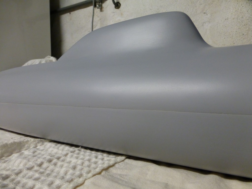
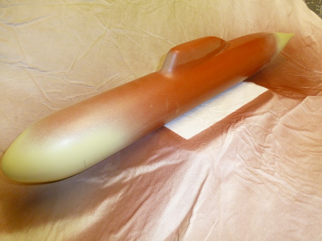
    Next step was applying several coats of automotive primer to the masters and preparing them for molding. The masters in the picture below were wet sanded with 600 and finally with 1200 gri sandpaper.
    Close-up sail trailing edge finished.

    Akula 1/144 scratch build Akula_26

    Close-up sail corner with flat deck.

    Akula 1/144 scratch build Akula_27

    Close-up view of the seam.

    Akula 1/144 scratch build Akula_25

    General view after sanding with the 1200 grid.

    Akula 1/144 scratch build Akula_28

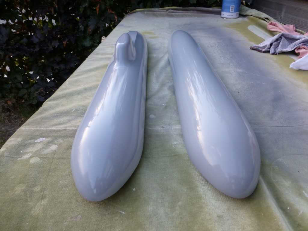
    The masters were prepared, polishing with automotive polish several times until one could use them as an mirror. Next I have applied the release wax, 5 coats in total, polishing the masters between the coats.

    Akula 1/144 scratch build Akula_30

    Akula 1/144 scratch build Akula_31

    Akula 1/144 scratch build Akula_32

    Masters ready

    Grtz,
    Bart
    bwi
    bwi
    AMS member


    Posts : 81
    Join date : 2015-01-17
    Location : Belgium

    Akula 1/144 scratch build Empty Making the molds

    Post  bwi Sat Jan 17, 2015 11:40 pm

    Making the molds:
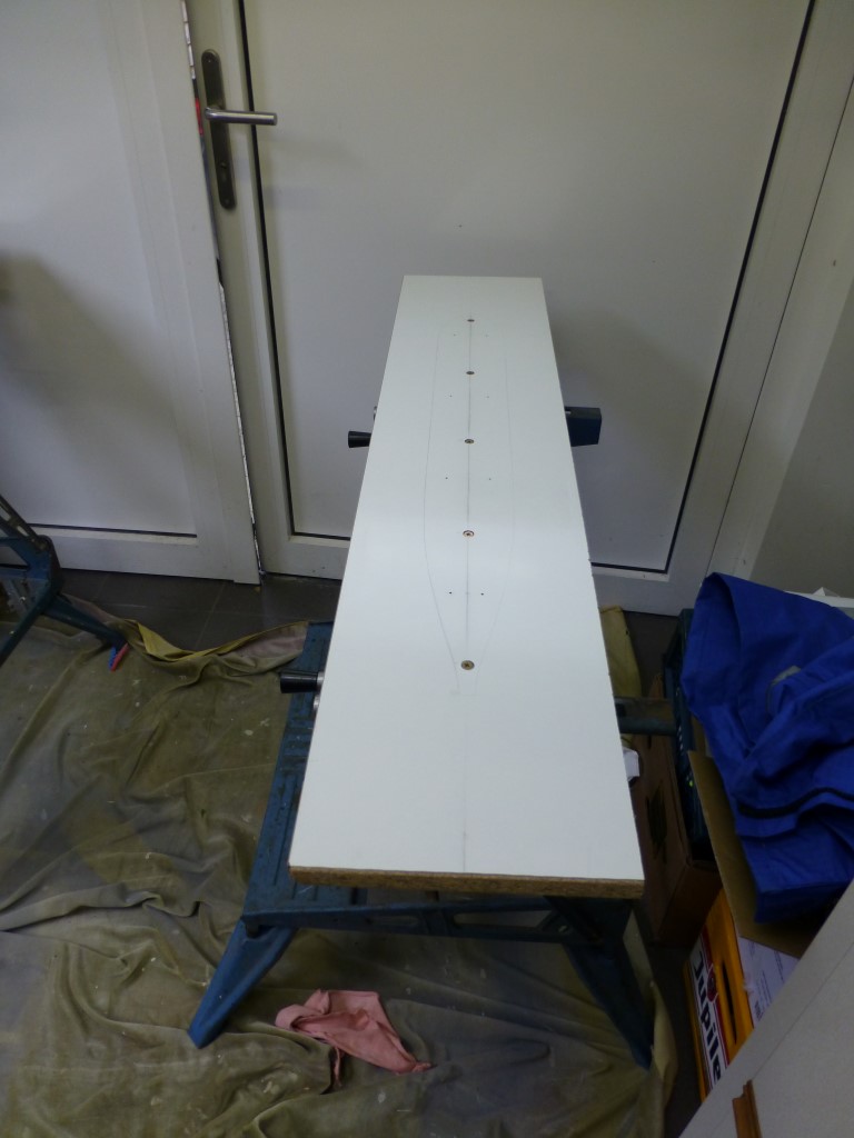
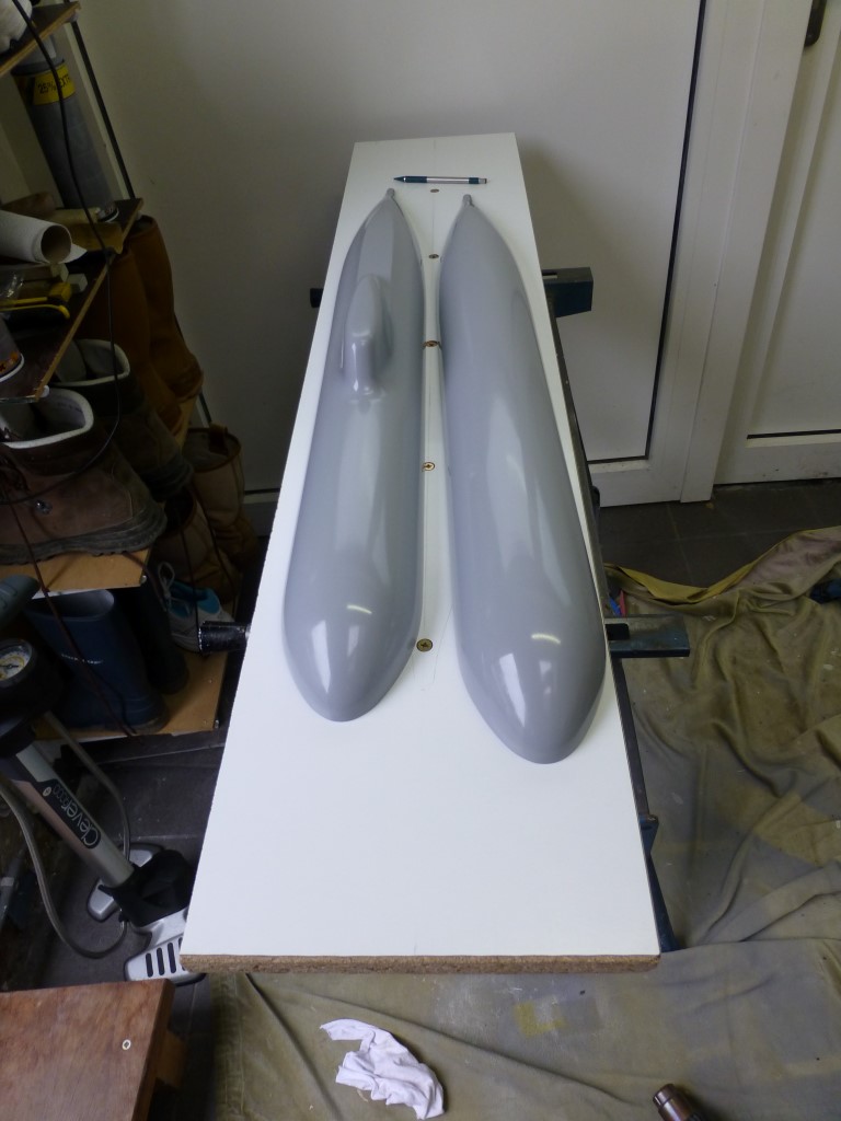
    I have made the mold boards out of laminated hardboard; I have reinforced it by means of a longitudinal piece of the same hardboard.

    Akula 1/144 scratch build Akula_33

    Akula 1/144 scratch build Akula_34

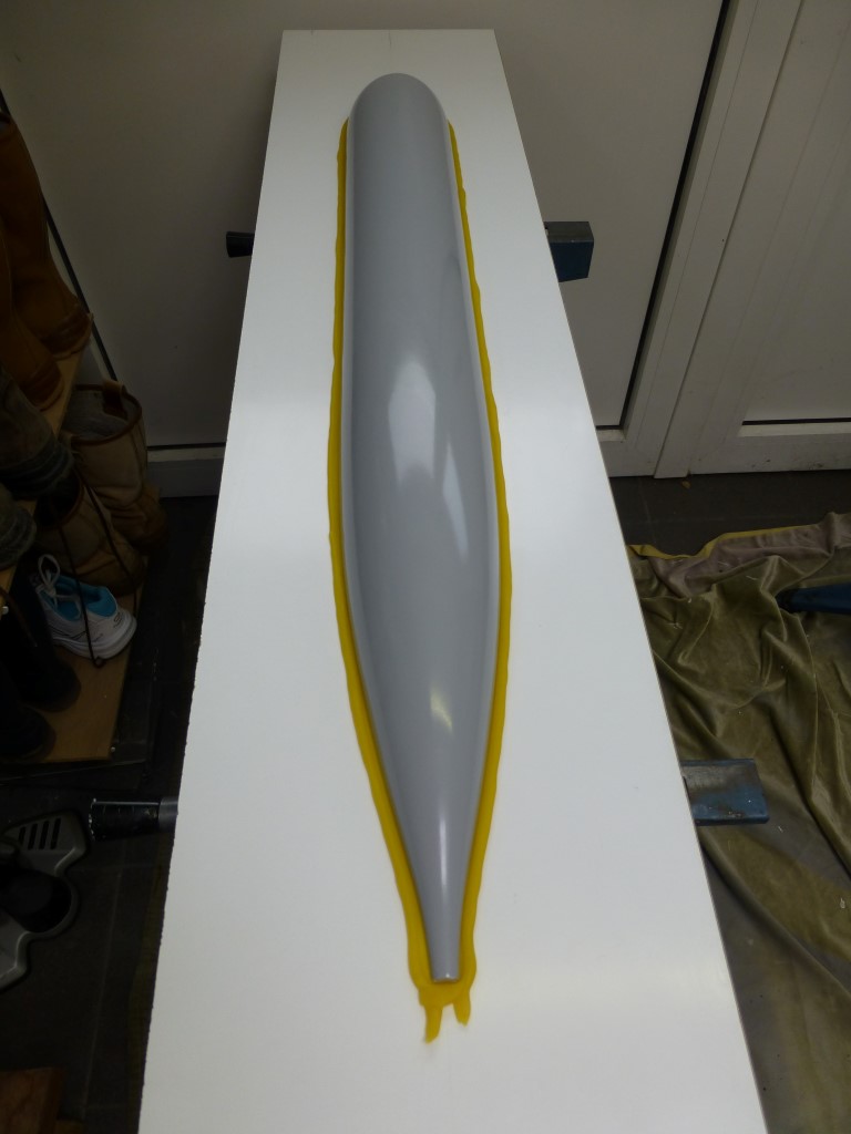
    The master were presented to the mold board and the contours were copied to the mold board by pencil. I was pondering about how to attach the master to the board. In first wanted the use screws but let the idea go. Finally I have opted to use some special modeling clay, when it is heated (microwave) the stuff becomes really soft almost in a liquid state. My intention was to heat the modeling clay, make a string, apply the string on the molding board following the contours in pencil, then to press the masters onto the molding board squeezing the modeling clay. I had to make another approach because the moment the modeling clay made contact with de cold board the clay hardened and could not be squeezed anymore. So finally I made thin strings of modeling clay, laid it on the molding board on the contours and heated the stuff up with a paint stripper until it became really soft then pressed the master on the molding boards. The modeling clay squeezed out nicely and the after it was cured the masters were perfectly attached to the board. The excess of the clay was cut away leaving an nice seem between the board and the masters.

    Akula 1/144 scratch build Akula_35

    Akula 1/144 scratch build Akula_36

    Akula 1/144 scratch build Akula_37

    To make the molds I have purchased two 2 m² of 150gr glassfibre cloth, 1 kg of gel coat, 2kg of polyester resin, release wax and release liquid.

    I had also purchased an good quality half face reusable respirator with adequate filter elements to protect myself against the nice vapor of the polyester resins.

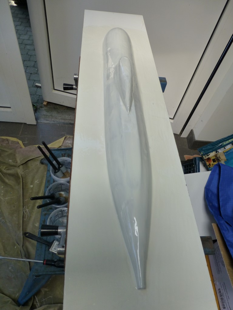
    I have applied the release liquid with a soft cloth. The masters were ready to receive the gel coat…..it was really strange to cover the nice and shiny master with the gel coat logically one expect this will turn out really bad.

    I laid down two coats of gel coat with the necessary curing time in-between, then applied the polyester resin with the cloth. After the last coat was applied on the 2nd master I started to clean up everything. It has been a long day, started at 8h00 and finished at 22h00. When I picked up the measurement can for the hardener my hart jumped over a few times I noted the hardener of the last coat was still in the can…..After some nice vocabulary that lasted several minutes I took the decision to apply pure hardener with a bruch on the last coat of resin and hoped for the best.

    The next day (very early in the morning) I rushed to the garage to see if my attempt to rectify my stupid mistake worked. I was surprised to see that it had worked quite well, only some miner spots on the 2nd master mold were not cured.

    gel coat applied
    Akula 1/144 scratch build Akula_38

    Resin with cloth applied
    Akula 1/144 scratch build Akula_41

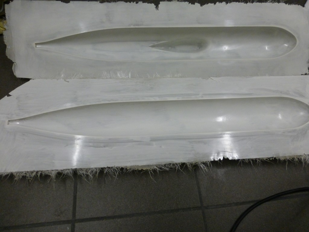
    I left the everything cure further fore Five days, then I tried to extract the masters out of the molds. At first I thought that everything was clued to each other I could not remove the masters, but with some gently applied force (read: red face, pumping vains) I managed to removed them. I was a little disappointed to see that pieces of the master remained in the mold, what went wrong?

    I place the whole in my boot and drove to the Polyester store for advice. First of all he told me that for a first mold it was a very good result, I told him I did everything by the book. He suspected that de automotive paint did not cope with the resin of the polyester as it is an one component paint.

    After the molds were cleaned and the pieces of the master removed (gently sanded), I was pleased with the result. But the clueing of the master to the mold kept crossing my mind. The paint is protected by the wax and I had applied 5 layers? I applied a layer of wax on a undamaged part of the master and polished it as I did before. I inspected the surface of the master and found it was shining but could not find any trace of the wax, I had polished so hard that I had removed the wax! Now I had found what I have done wrong. This lesson I will remember when waxing the molds.

    What I also noted on my molds is traces (brush marks) of the release liquid, even though I used a cloth to apply the liquid. So for making the actual hulls I will spray the release liquid to the molds. But I did not have an air compressor (it was still on my which list).

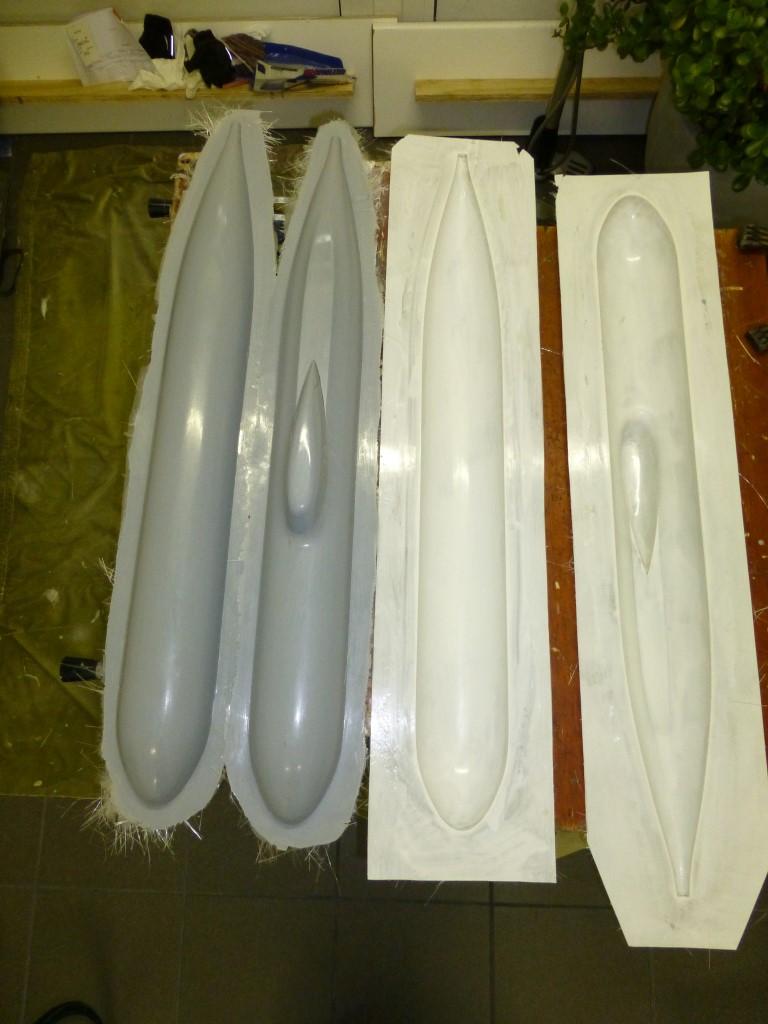
    Molds after cleaning
    Akula 1/144 scratch build Akula_39

    Damage to the masters
    Akula 1/144 scratch build Akula_40

    Molds finished

    Grtz
    Bart
    bwi
    bwi
    AMS member


    Posts : 81
    Join date : 2015-01-17
    Location : Belgium

    Akula 1/144 scratch build Empty Upper and Lower hull

    Post  bwi Sun Jan 18, 2015 12:18 am

    Upper and lower Hull

    As it was wintertime over here I turned the garage into a artificial tropical greenhouse using an electric heater. The temperature was a constant 20°C, exact what was needed to work with glassfiber resin.

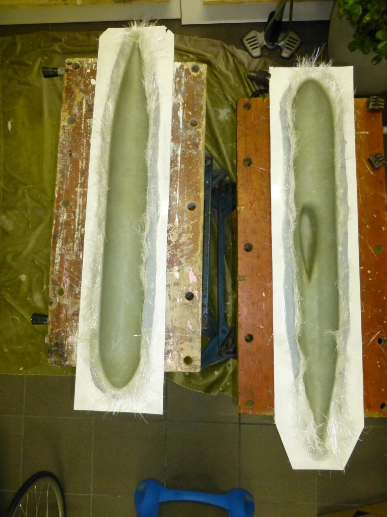
    I waxed the molds (this time I didn’t polish the wax off). I applied 2 layers of gelcoat (with grey pigment) and 2 layers of 300 g/m² glassfibre cloth.

    Akula 1/144 scratch build Akula_42

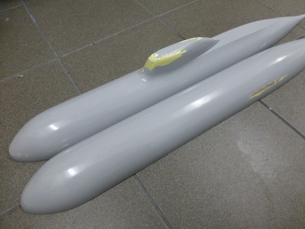
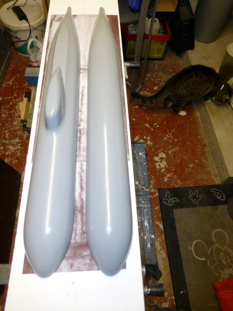
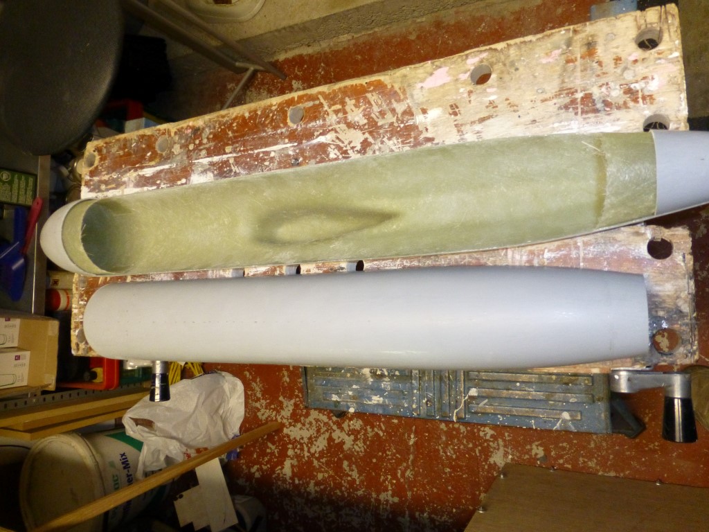
    Waited two days to let everything cure. The hull parted very easily from the mold this time, no gluing at all. The hull stiffness is OK and so is the weight.

    Akula 1/144 scratch build Akula_43

    Akula 1/144 scratch build Akula_44

    My first DIY hull is a fact! I’m very pleased with the result.

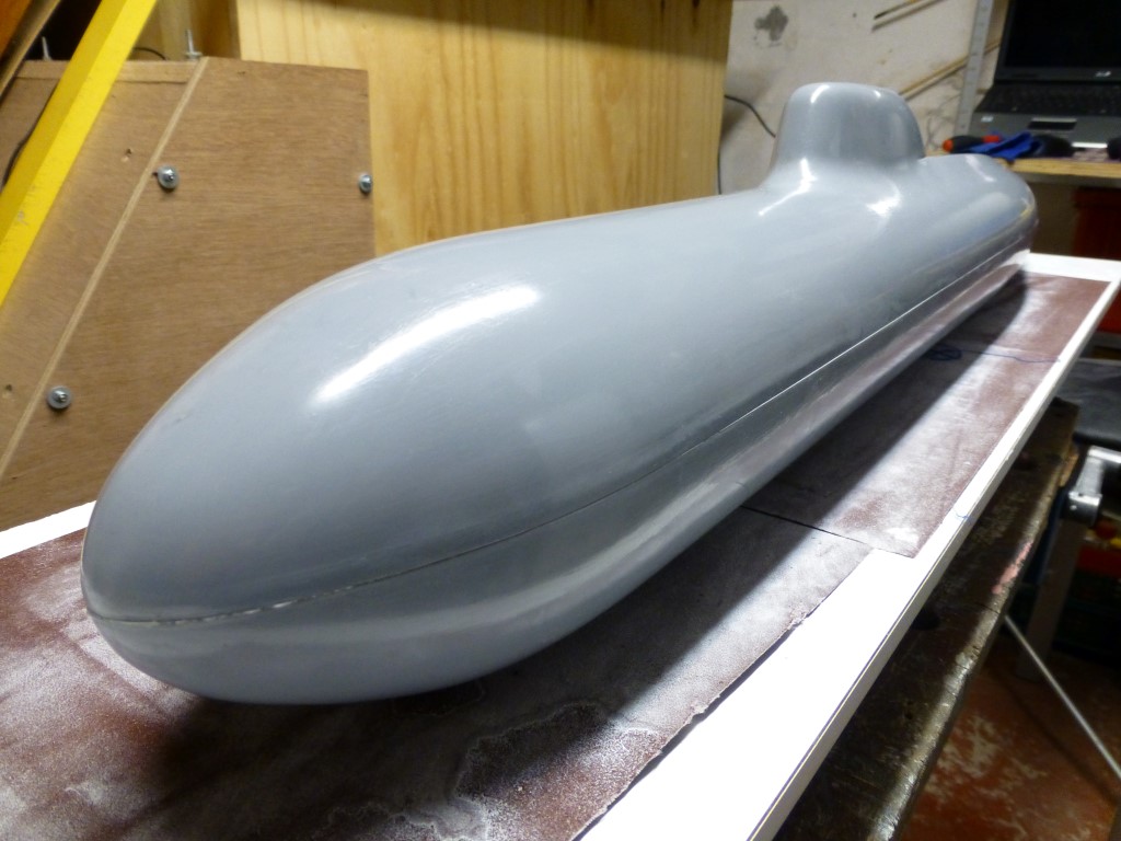
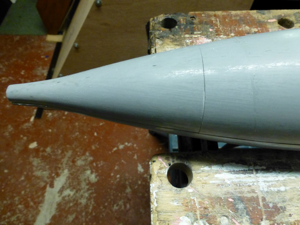
    Both hull parts were trimmed with dremel cutoff disks. The hull parts were sanded on a flat surface to make them fit together as good as possible. This worked out fine. I have only a gap (1mm) that I have to rectify. Hull part were wet sanded with 1200 grid paper (surface is to smooth to draw on it by pencil).

    Akula 1/144 scratch build Akula_74

    Akula 1/144 scratch build Akula_77

    Next thing to do was to cut the lower hull in 3 pieces, quite an terrifying thought after all that work. First I had to determine were I would make the cuts, for the Fwd my first idea was to make the cut iwo the front of the side sonar area, but this was too far to the aft, I would run into trouble to get the WTC into place. So I decided to make the cut at the Aft of the sonar area at the bow.

    The Aft cut I decided to make just in front were the tail fins ended. The centerline en cut lines were established by a laser (If you rebuild your house you remain with nice leftovers for your hobby afterwards).

    Akula 1/144 scratch build Akula_78

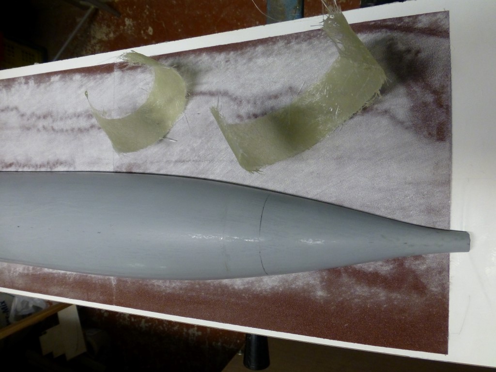
    Before the lower hull was cut I prepared the index lips needed at the sections afterwards. I made the index lips out of polyester resin and 2 layers of 300gr fibreglass cloth. I took over Davit Merrimen’s idea to make them the way I did. First I attached some wax paper to the hull i.w.o. the indicated cut lines. On top I laid-up the fibreglass so the hull shape is exactly transited to the fibreglass. After curing the wax paper was removed and after trimming the fibreglass you remain with very nice and easy to install index lips.

    As I didn’t had a clue where to find the waxpaper and I did not want to spent half a day looking for it in nearby shops, I shut down all my vital body functions and used that brain cell to pounder if I could use something else. And yes it worked, I think everybody has la label paper roll somewhere in house, well I thought if the labels don’ t stick to the paper is must be some kidt of waxpaper, I remove a label and tested it out with a drop of CA adhesive and it worked, after curing the drop could easily be peeled off the paper.

    Akula 1/144 scratch build Akula_80

    Akula 1/144 scratch build Akula_81

    Akula 1/144 scratch build Akula_82

    Akula 1/144 scratch build Akula_83

    The cuts were made using my Scroll Saw, five minutes of concentration a the job was done.

    Akula 1/144 scratch build Akula_87

    Akula 1/144 scratch build Akula_88

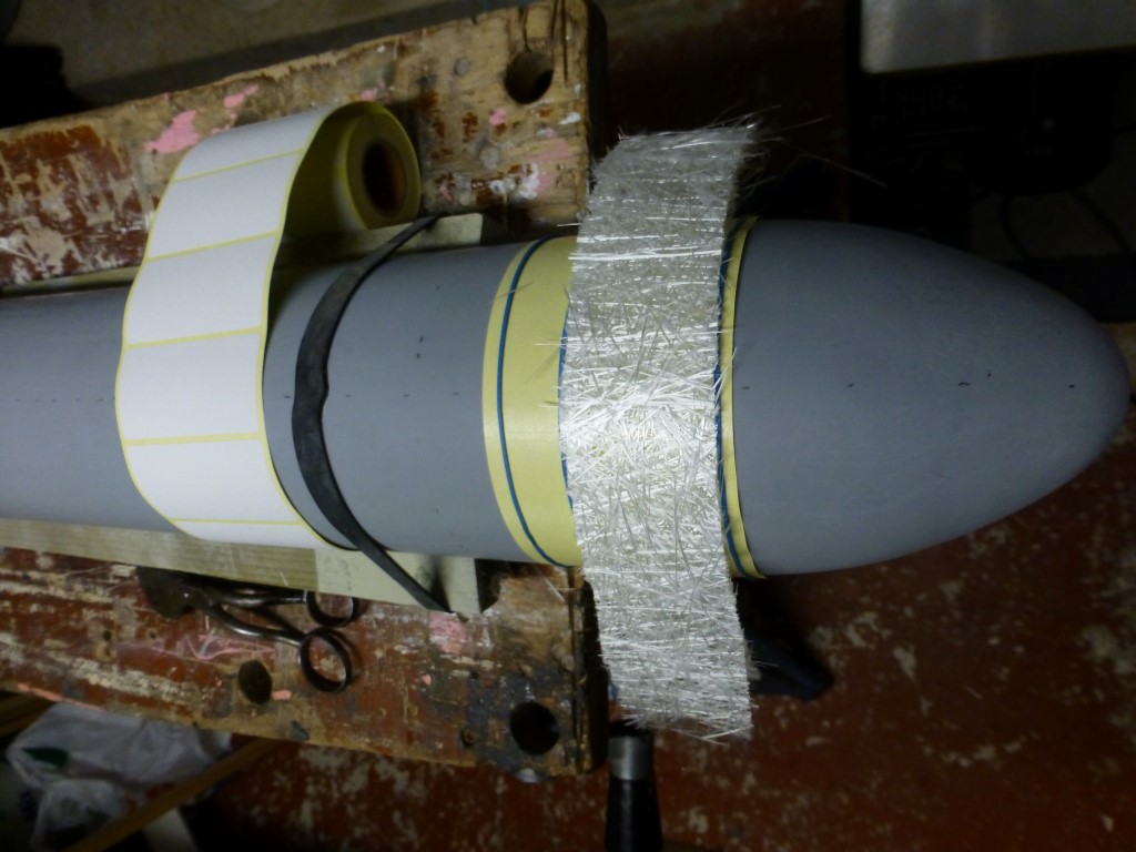
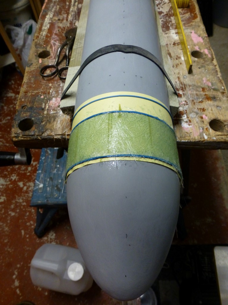
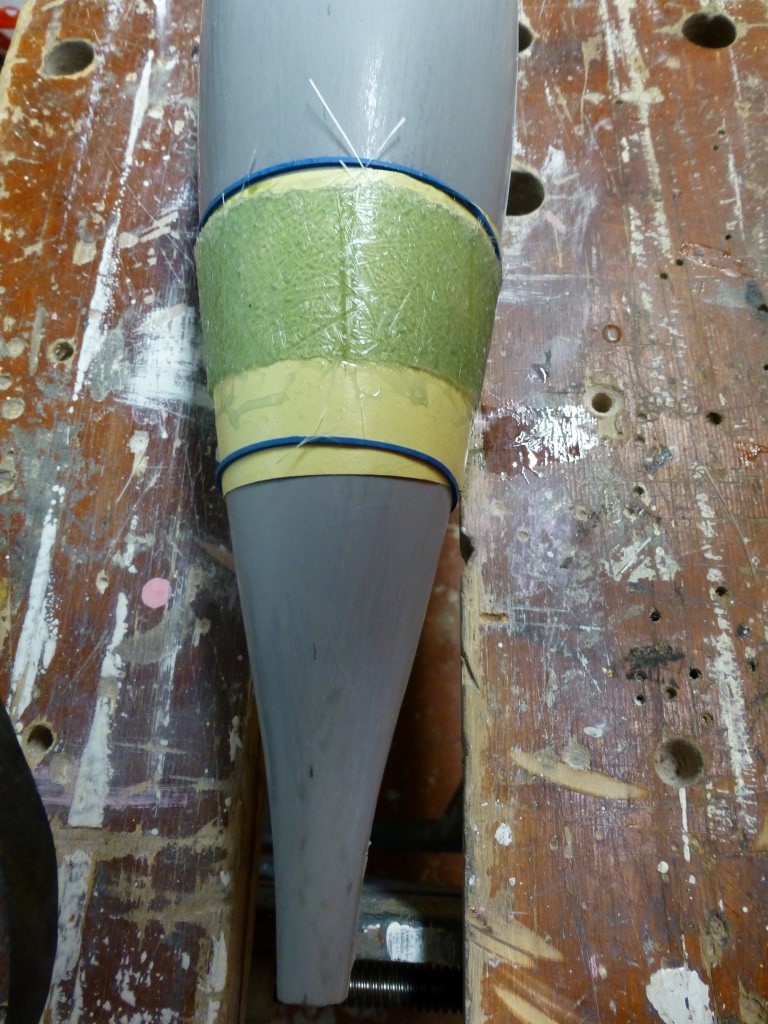
    The bow and stern were assembled and tagged with CA glue. The middle piece was try fitted. After that the bow and stern were permanently attached with CA glue the seam was reinforced from the inside with fiberglass cloth and polyester resin.

    The Fwd and aft index lips were glued in place with epoxy glue.

    Akula 1/144 scratch build Akula_85

    PS & SB index lips were constructed the same as the Fwd an aft lips, all glued in place with epoxy glue.

    Akula 1/144 scratch build Akula_89

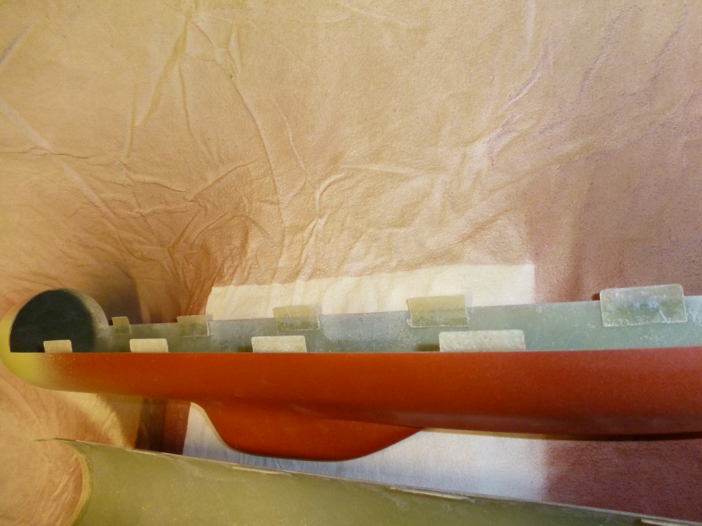
    At first I glued the indexes to the upper part of the hull, it turned out to be an bad idea. It was impossible to get de seam of the upper end lower hull nice in line due to the fact that the thickness of the hull halves differed. I removed the indexes (nice job when all is glued with epoxy) made new indexes cut them in 3cm long (1”) pieces en glued them alternating to the upper and lower hull. It took me some time but eventually I managed the get hulls lined up nicely.

    Akula 1/144 scratch build Akula_90

    Akula 1/144 scratch build Akula_91

    Akula 1/144 scratch build Akula_94

    For the propeller shaft assembly I used the techniques of David Merriman.
    The propeller shaft bushings in sinter bronze were ordered and arrived. A dummy caliber was turned at the diameter of the bushings. The dummy was centered in the stern. The fish was placed vertical. Polyester resin was poured into the stern the excess was able to drain trough a previous drilled hole. After the resin had cured the caliber was removed.

    As earlier stated the stern did not fit perfectly together, I closed the seam with CA glue in order to pour the resin in without leaking through the seam. However the gap resulted that the aft part of the stern was not cylindrical anymore but more of an oval. This could not be rectified until the stern was filed up with the resin. I spent a lot of time to make things cylindrical again and at the same time match the diameter of the bushing.

    Akula 1/144 scratch build Akula_92

    The hulls were sanded and painted several times and are waiting to get scribed.

    Grtz,
    Bart
    bwi
    bwi
    AMS member


    Posts : 81
    Join date : 2015-01-17
    Location : Belgium

    Akula 1/144 scratch build Empty The Propeller

    Post  bwi Sun Jan 18, 2015 11:42 am

    The propeller:

    I’m familiar with propellers in real life but I never have seen a submarine prop in real time, just on pictures. I thought this would be a nice side project to build a subprop in 1/144 scale.

    I wanted some more information on the pitch and the diameter of the submarine propellers. I knew there must be something about propellers in the some old magazines and found some very interesting articles about the subject.

    "The engine room by Robert Hughes and friends"
    "model submarine propeller theory, design, and fabrication by David Merriman"
    "yet another way to make propellers by David Merriman"

    I studied the pictures I have of the props, it is really hard to tell the exact shape of the blade area as the angle in which the picture was taken deforms the shape of the blade. I had one good picture almost taken at the height of the hub. I have imported the picture in google sketchup and traced the blade shape, that was one les worry. The blade area turned out to be 70% what was ok according to the articles.

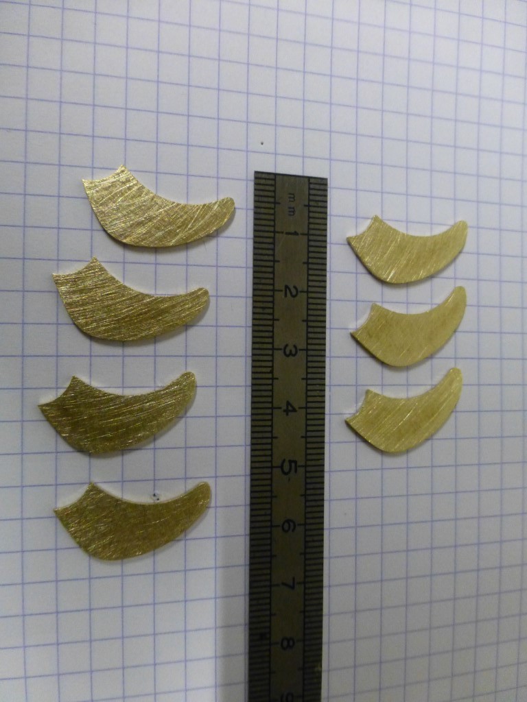
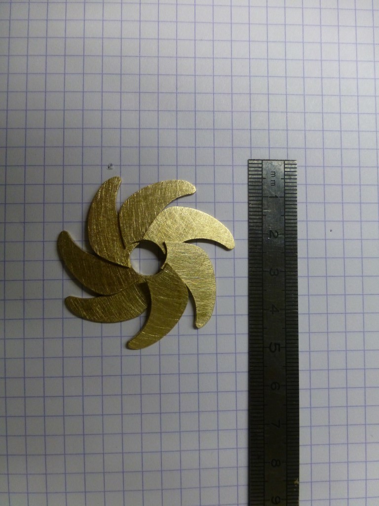
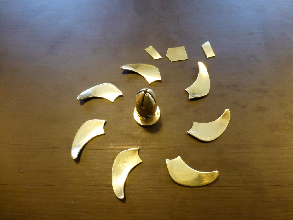
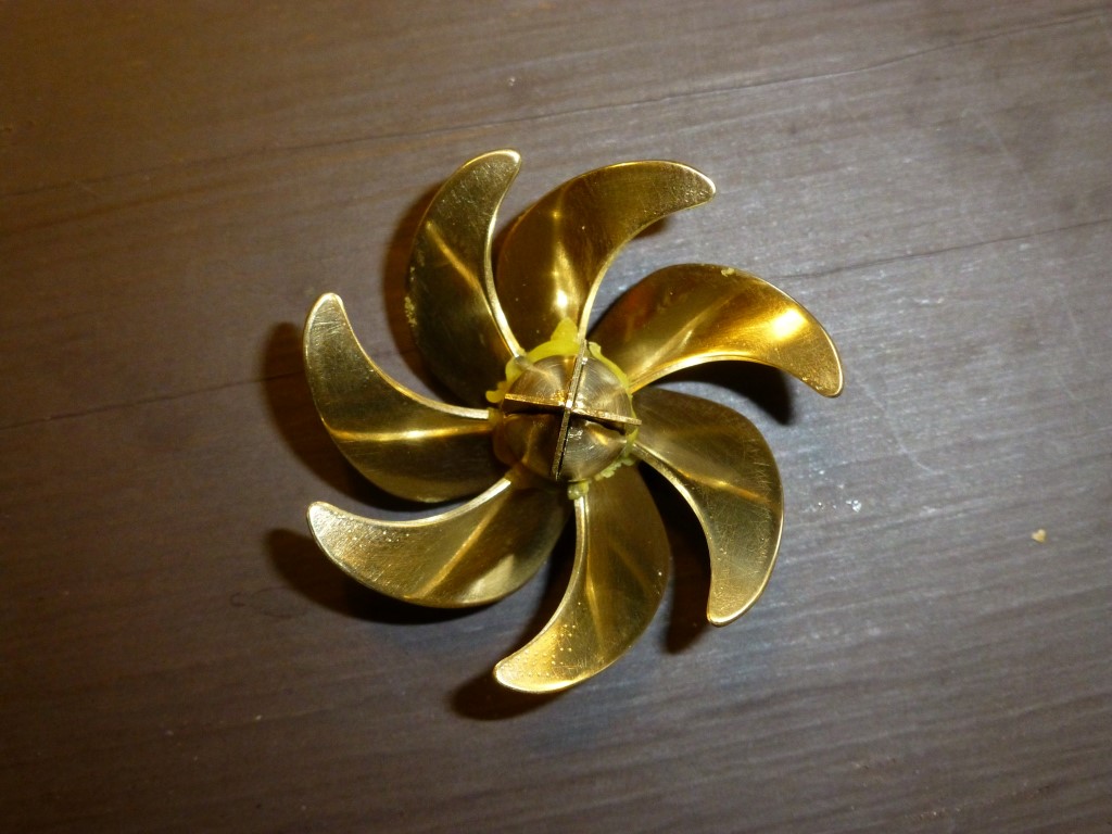
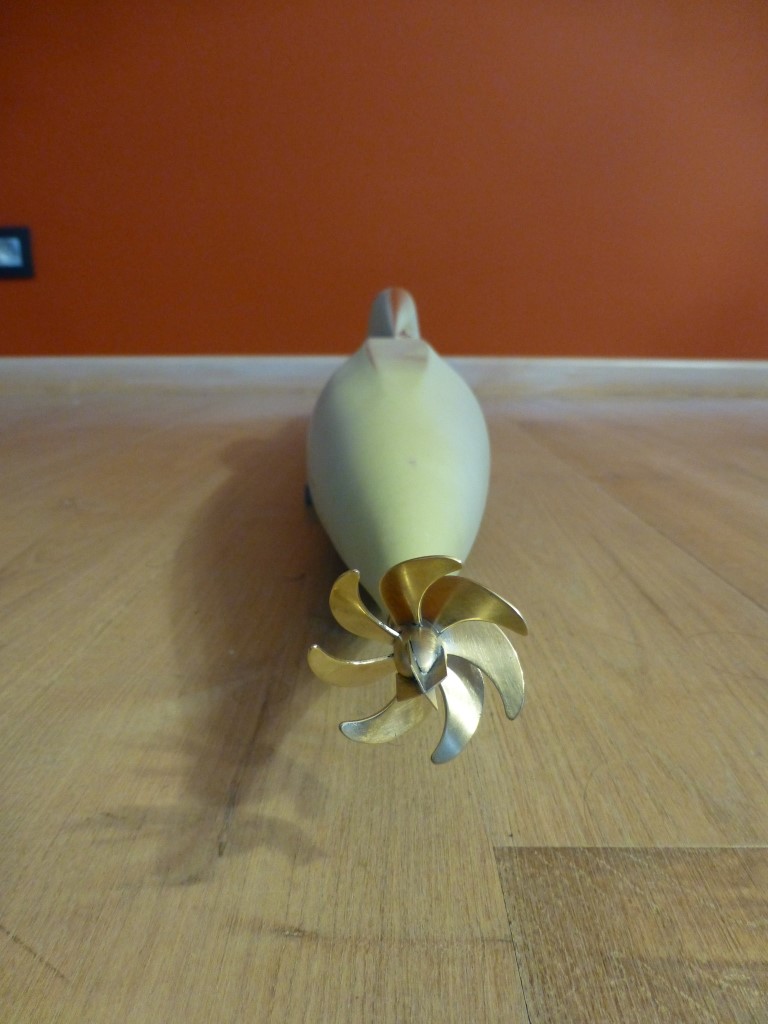
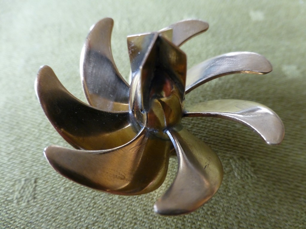
    I decided not to cast the propeller but to make the propeller out of brass. The prop will be  diameter 43mm. The 7 blades were cut out a 1mm thick brass sheet. The hub, diameter 10mm with a length of 21mm, was turned on the lathe.

    Akula 1/144 scratch build Akula_47

    Akula 1/144 scratch build Akula_49

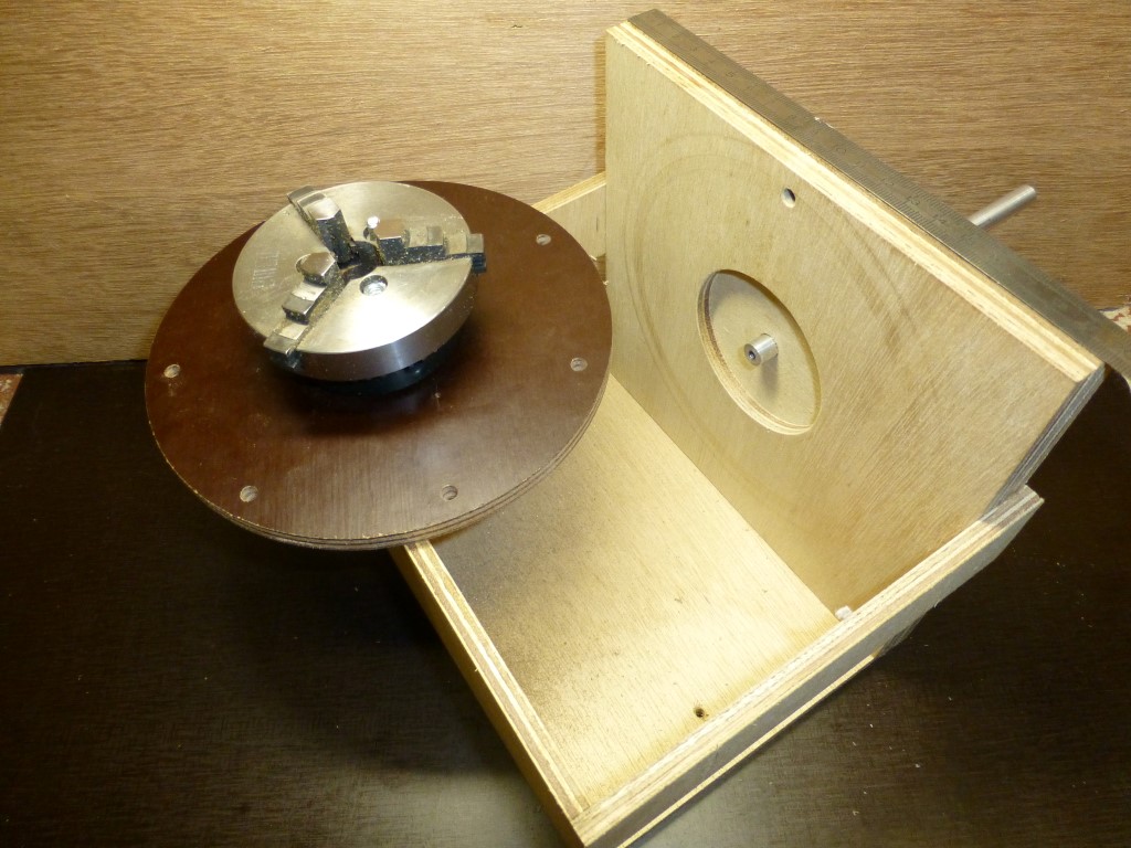
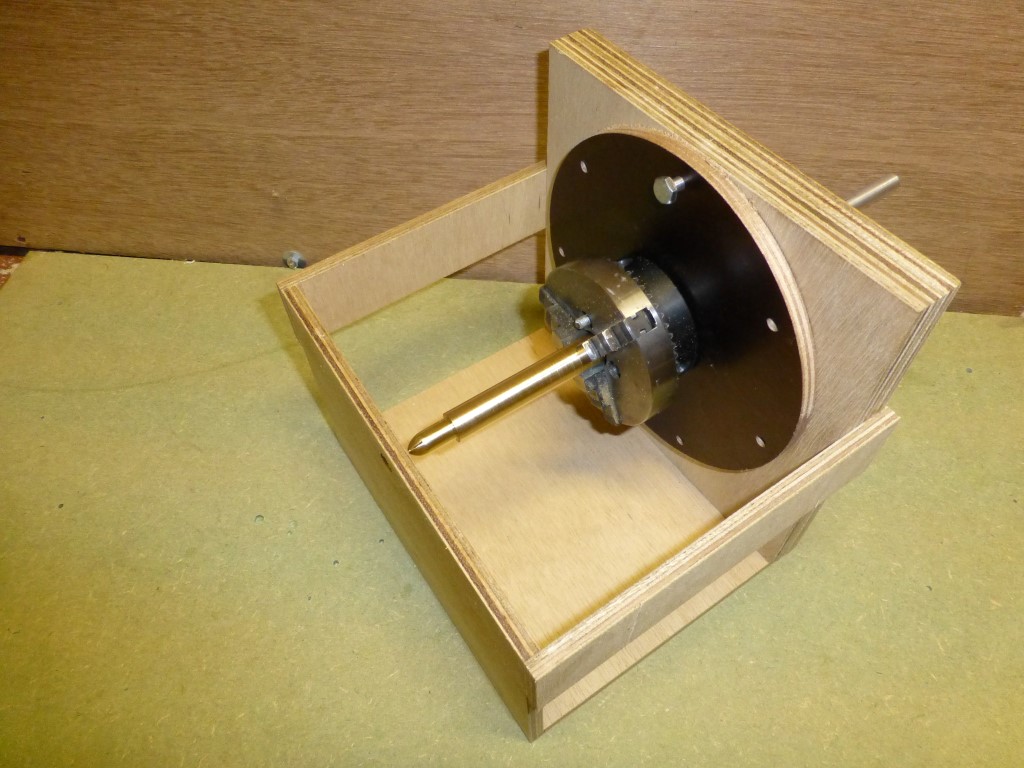
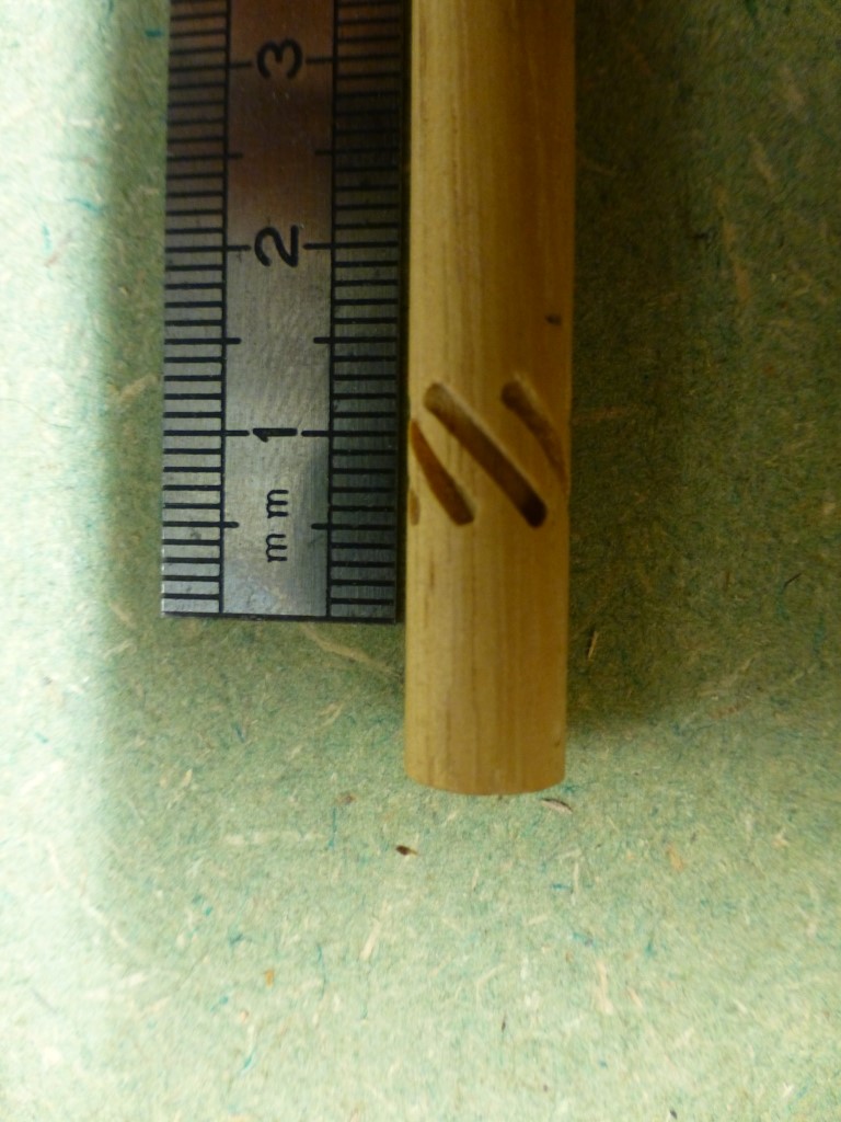
    In order to make the 7 cuts in the hub that retain the blades I made a division aide, a circle was cut out of plywood, the disk was divided into 7; and 7 holes were drilled; in the center I have mounted the chuck of my lathe. A support was made from plywood all glued together. The vertical part was also provided with a hole at the same radius as of the plywood disk. The disk is connected to the support and rotates on it by means of a 10mm axel. When I put the brass hub in the drill chuck I can rotate the circle plate until the next hole mates with the hole in the support, put a taper pin in it and mill the first sleeve in the hub. For the next sleeve I rotate the circle plate until the next hole matches with the hole in the support….I did this 7 times and it worked fine. Before you start milling the sleeves you have to calculate the blade angle at the blade root.

    Akula 1/144 scratch build Akula_53

    Akula 1/144 scratch build Akula_56

    I was in doubt for a long time about the diameter of the hub 10 or 8mm, as I had to do a test with the jig I used a 8mm piece of wood; the test was ok but the 8mm was to small compared with the blade dimensions.

    Akula 1/144 scratch build Akula_55

    The sleeves are 1mm wide and 8mm in length.

    Akula 1/144 scratch build Akula_58

    Next step was to twist the blades in order to get the desired blade angle at a given radius. I had already calculated the angle at the blade root and now I had to calculate the angle at the blade tip. I twisted the blade tip matching the desired angle making sure that the twist is equally over the entire blade length.

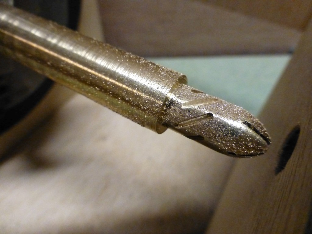
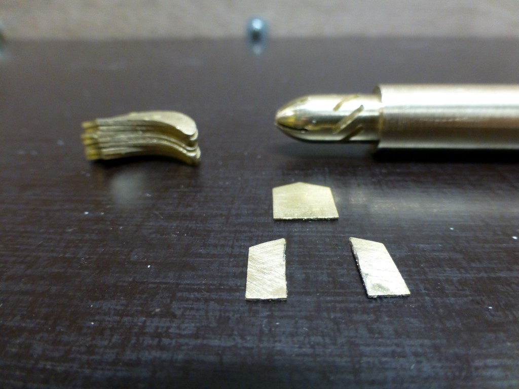
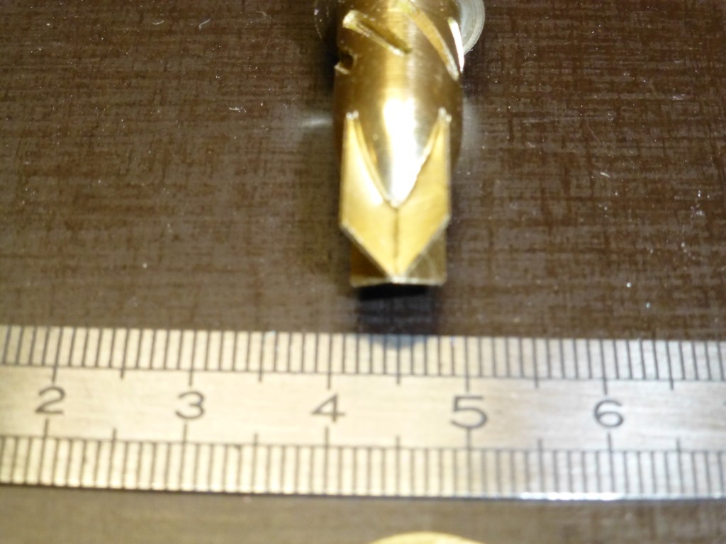
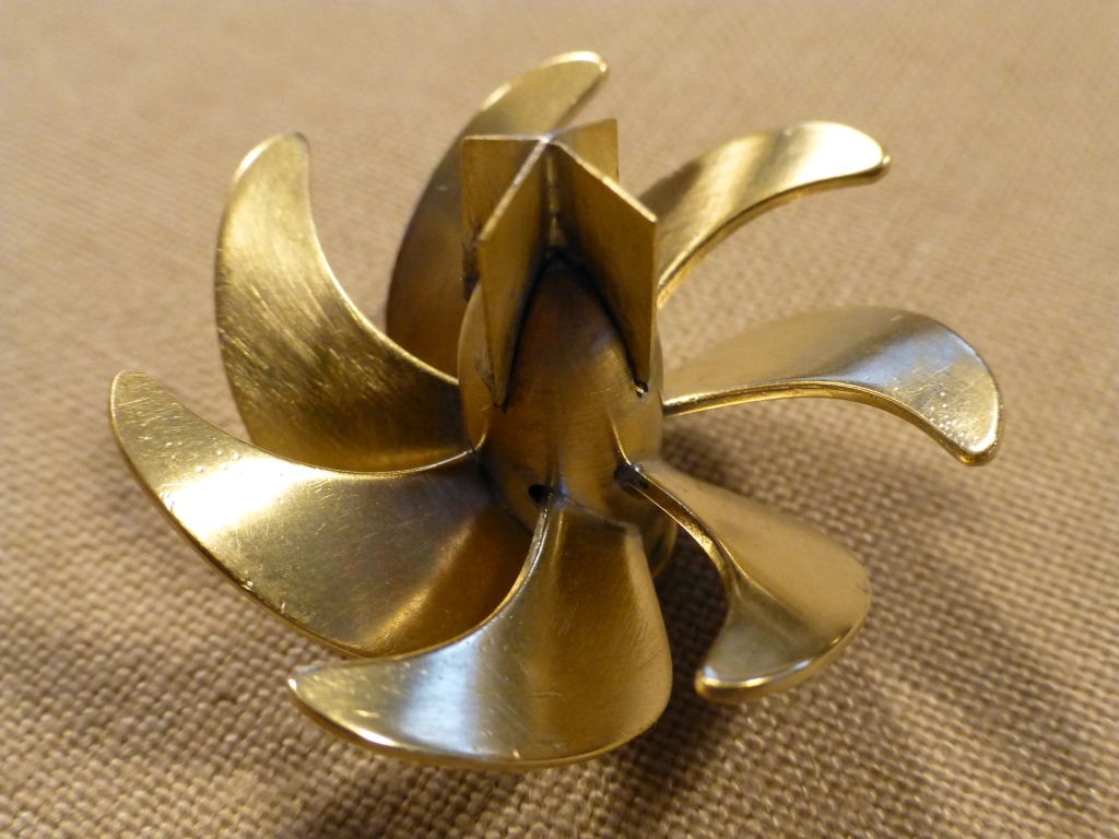
    The Russian subprops have a attenuator on in front of the hub. To cut sleeves in the hub I used a jigsaw; the blade thickness was 0.4mm. It took some patience and determination to cut the sleeves in the 10mm thick brass but it turned out fine. The attenuator plates ware cut out 0.4mm thick brass sheet. One of them was cut longitudinal in halve.

    Akula 1/144 scratch build Akula_62

    Akula 1/144 scratch build Akula_50

    Akula 1/144 scratch build Akula_60

    Akula 1/144 scratch build Akula_61

    The hub was cut to length on the lathe leaving a collar at the back. My intention is to adjust the diameter of the collar to the diameter of the actual stern-tube collar.
    That is the reason I will not solder the prop together yet, if I do I can’t adjust the collar diameter on the lathe.
    All part were cleaned up and polished.

    Akula 1/144 scratch build Akula_68

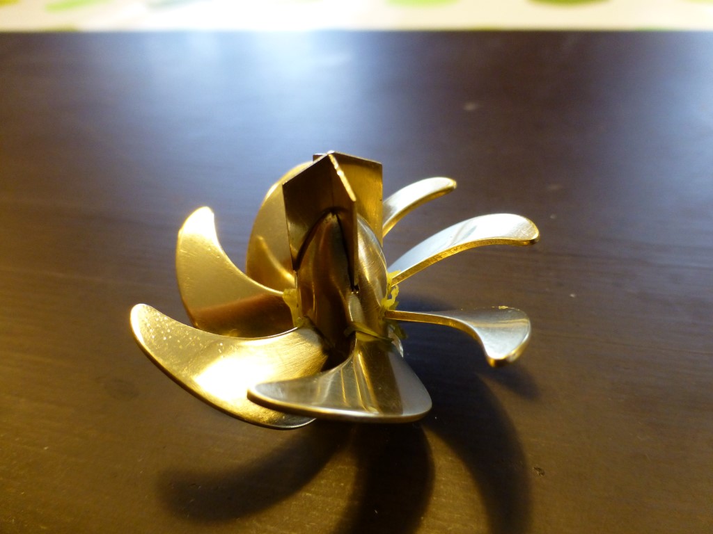
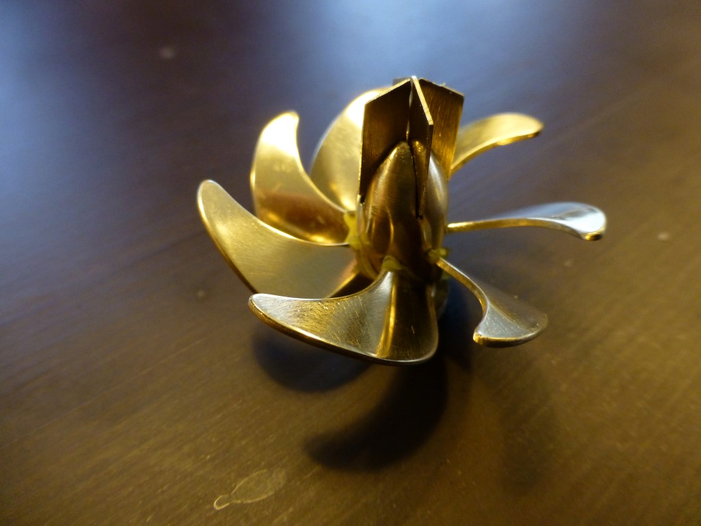
    But I could not wait till then to actual see the prop all together so I filled the blade sleeves of the hub with some modeling clay and pushed the blades in place, and all the effort played off with the view I got.

    Akula 1/144 scratch build Akula_69

    Akula 1/144 scratch build Akula_71

    Akula 1/144 scratch build Akula_72

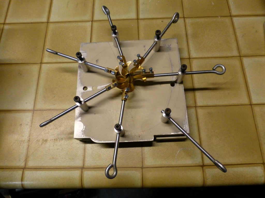
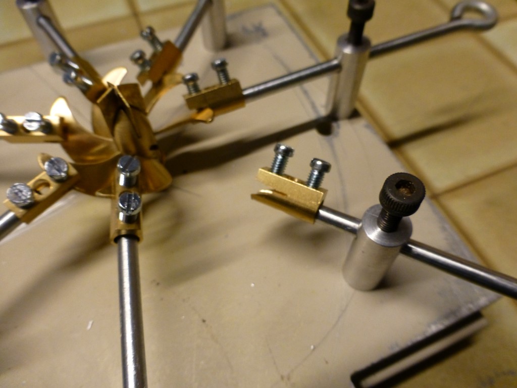
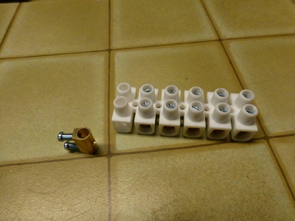
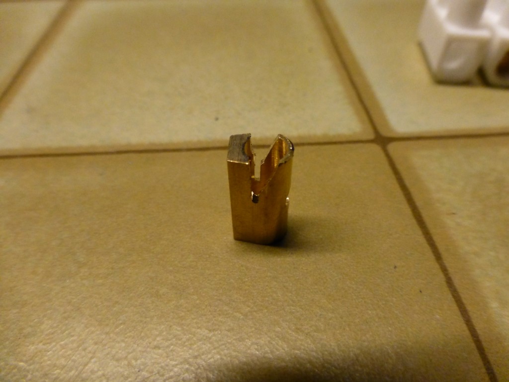
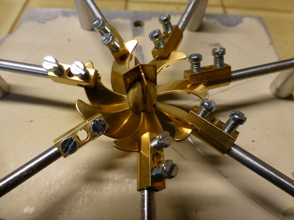
    The diameter of the collar on the prop hub was adjusted to match the diameter of the stern-tube bushing. In order to solder the prop, a solder jig was made as per Robert Hughes example. I have made mine from aluminum. The seven posts (dia10 x 25mm) are mounted to the baseplate by M4 bolts. A 4mm hole is made in the posts to support the arms, a set screw allows the arms to be fixate into the posts. At the end of the arms a modified screw terminal block is attached, the grinded V-slot can receive the blade, the blade can be fixated by the small screw.

    Akula 1/144 scratch build Akula_95

    Akula 1/144 scratch build Akula_98

    Akula 1/144 scratch build Akula_96

    Akula 1/144 scratch build Akula_97

    Akula 1/144 scratch build Akula_99

    Soldering the prop:

    I used solder with a flux core. This didn’t work at all, the solder did not flow nicely, as a matter in fact it didn’t flow at all resulting in a prop with clumps of solder sticking to it and to complete it all…..blades eventually popped out of the sleeves in the hub. I was so disappointed that I left the prop on the workbench for a couple of days. It looked really bad some of the blade were still not attached even with all that solder clumps sticking to the hub. When all the dust settled down the prop got my attention again. I decided to heat the lump of solder and retrieve all the parts and investigate if any of the prop parts were salvageable. I spent a couple of hours to clean all the blades, attenuator and the hub. The sleeves in the hub was the most difficult to clean, I did it by heating the hub and blow everything out with air pressure. Yes I worn safety googles but I hope nobody has do the same as I explain below how I manage to solder the prop the right way. To my relieve all the parts were reusable.

    I streamed the www and found out that the appliance of a separate flux was the way to go, just as you do with hard soldering (go figure……I have done my part of hard soldering when I was at sea). What I also learned is that some of the fluxes contain acid others don’t. You have to use the one without acid. I ordered my flux on the www and waited……until it dropped in the mailbox.

    I prepared the prop in the gig and went to work, applied the flux to all parts, heat everything up and applied the solder (as you have a separate flux you must not use solder with flux but just common solder) and YES YES YES it flowed soooo nicely. I almost say it’s word while the disappointment at the first attempt (but I suggest you skip the first attempt even though the happiness might be less intense).

    Akula 1/144 scratch build Akula_101

    Stern bushing:
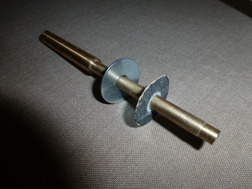
    I made a grinding device to get the stern plane perpendicular to the longitudinal axis of the sub doing so I get a perfect fit with the stern tube bushing. The dummy caliber for casting the stern tube was converted to a grinding jig, adding a washer with sandpaper glued to it. Insert the gig into the sterntube and twist it around and you get a perfect mating surface for the bushing.

    Akula 1/144 scratch build Akula_104

    Akula 1/144 scratch build Akula_105

    Akula 1/144 scratch build Akula_103

    Akula 1/144 scratch build Akula_106

    The last thing outstanding was to soften the cutting and trailing edges.

    Akula 1/144 scratch build Akula_148

    Propulsion line is ready

    grtz,
    Bart
    bwi
    bwi
    AMS member


    Posts : 81
    Join date : 2015-01-17
    Location : Belgium

    Akula 1/144 scratch build Empty Vacuum Tank & Pressure pot for casting

    Post  bwi Sun Jan 18, 2015 2:49 pm

    Prior to the casting process I needed an air compressor, vacuum tank and pressure pot.

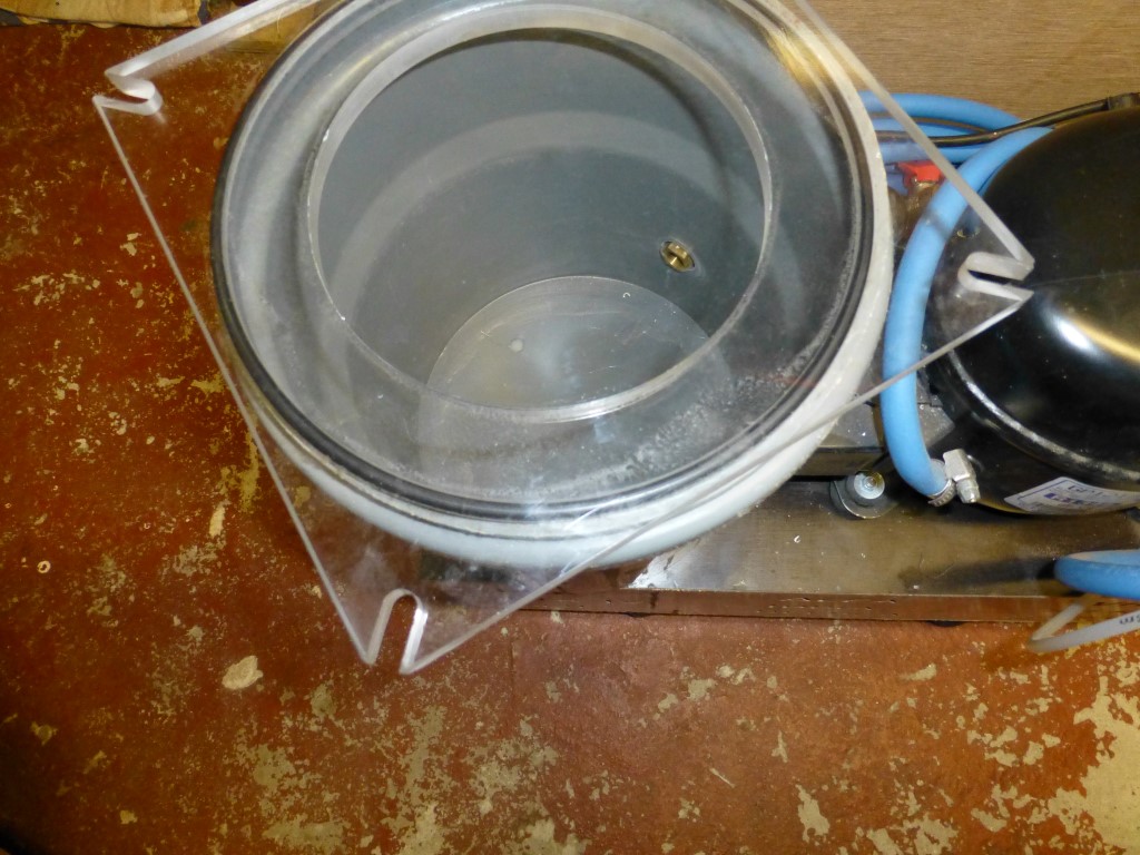
    The vacuum tank was made out of thick PVC the lid was made of Plexiglas so I could Cleary see the what is going on when degassing. The seal is an O-ring. The dimensions of the groove were calculated as per Andrew Lawrence direction I found on another forum. The vacuum tank is combined with my compressor meaning that I can deviate the suction of the compressor to the tank and create a vacuum that is sufficient to degassing the silicone mold casting resin.

    Akula 1/144 scratch build Akula_100

    Akula 1/144 scratch build Silent_air_compressor_DIY_1

    The pressure pot for casting I purchased at the www it’s a regular paint pressure tank of 2,25 Gallon/8.5 liter which I modified a little bit.

    Akula 1/144 scratch build Silent_air_compressor_DIY_8
    bwi
    bwi
    AMS member


    Posts : 81
    Join date : 2015-01-17
    Location : Belgium

    Akula 1/144 scratch build Empty Intake Scoop & SOCKS

    Post  bwi Sun Jan 18, 2015 2:53 pm

    Intake Scoop & SOCKS

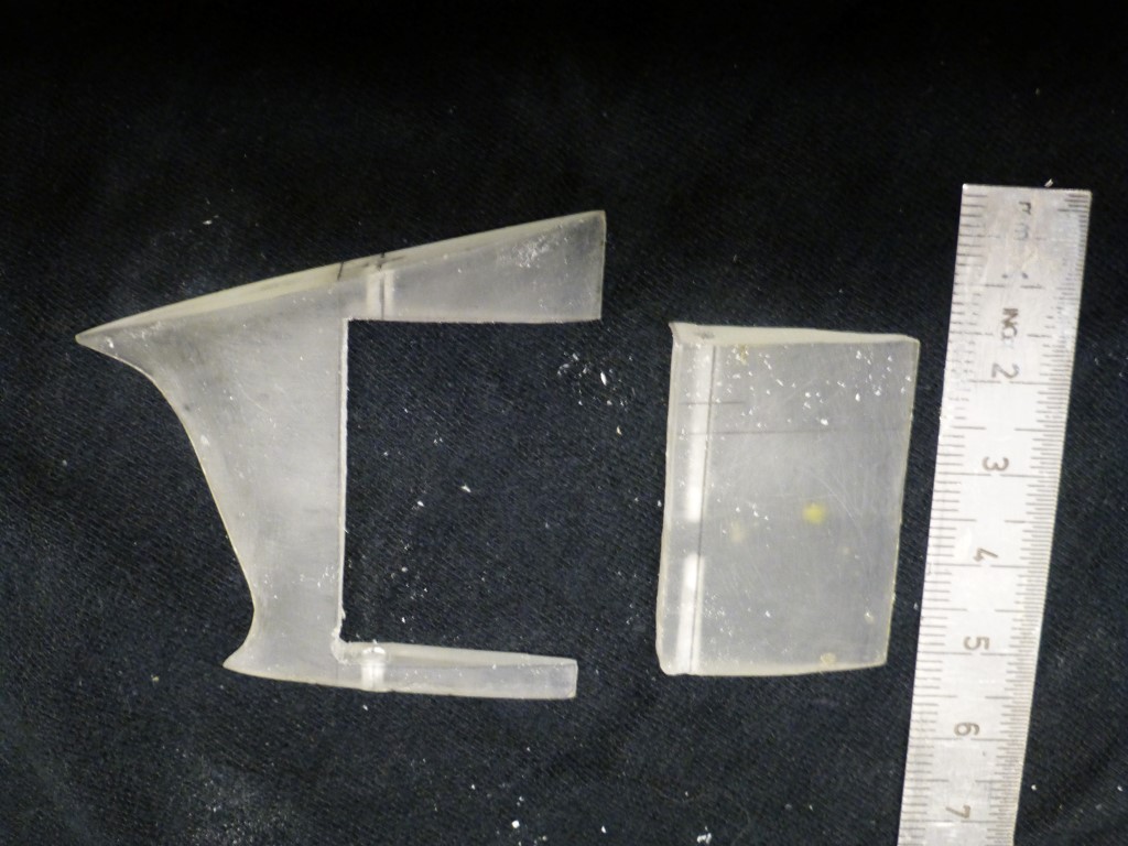
    The water intake scoop I have drawn up myself from pictures found on the web and in the book of Wayne Frey. They have been made out of two pieces of acrylate and grinded/sanded into shape.
    Next up were the SOCKS sensors, these I have crafted without any drawings just by means of pictures and some guested dimensions.

    Akula 1/144 scratch build Akula_6

    Akula 1/144 scratch build Akula_5

    I will cast all the above stuff in an later stadia of the project
    tattooed
    tattooed
    AMS member


    Posts : 340
    Join date : 2011-05-16
    Age : 61
    Location : Bristol

    Akula 1/144 scratch build Empty Re: Akula 1/144 scratch build

    Post  tattooed Sun Jan 18, 2015 3:10 pm

    fantastic workmanship, a true master at what you do. keep up the great work a fantastic thread
    bwi
    bwi
    AMS member


    Posts : 81
    Join date : 2015-01-17
    Location : Belgium

    Akula 1/144 scratch build Empty Rudders, Planes & Towed array pot

    Post  bwi Sun Jan 18, 2015 3:52 pm

    Rudders, Planes & Towed array pot

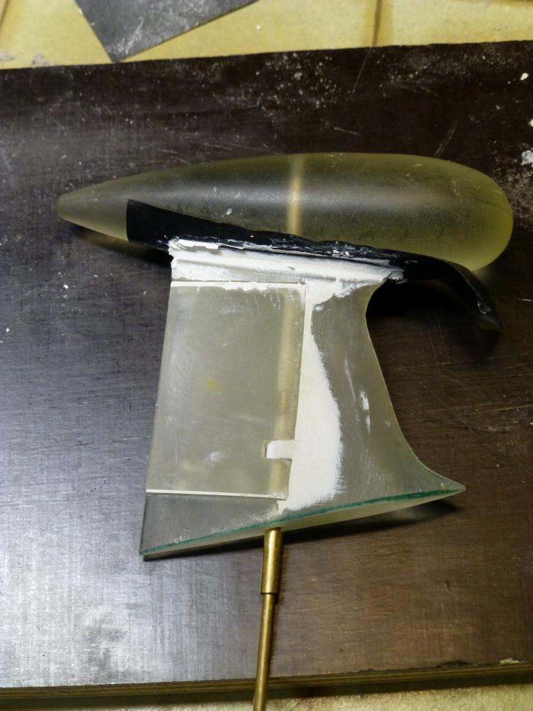
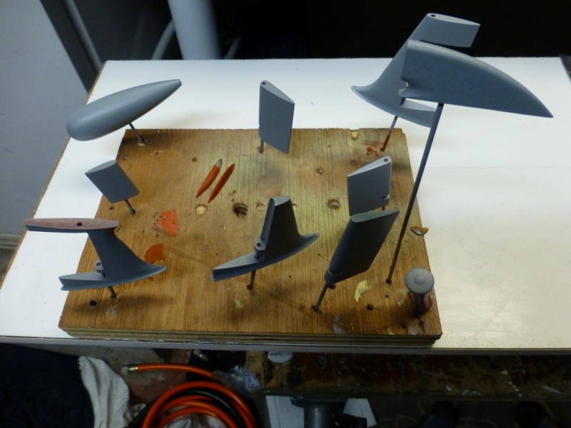
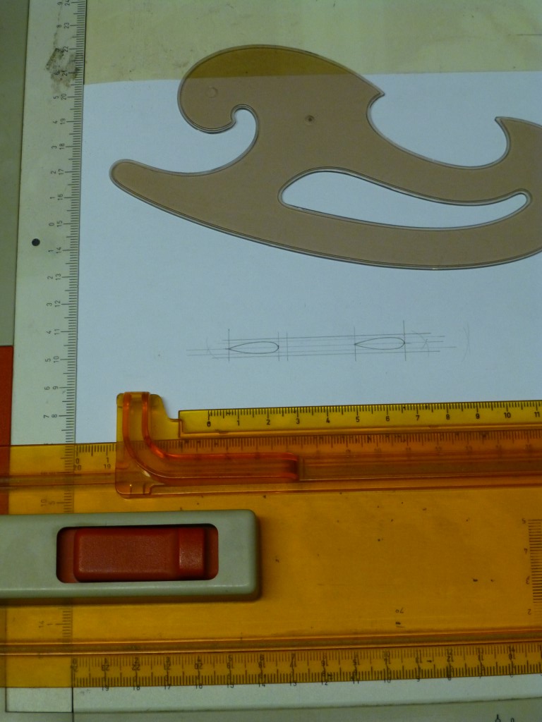
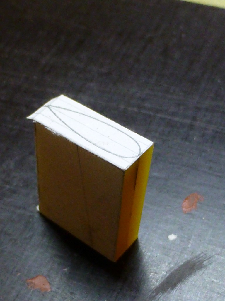
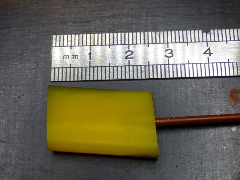
    In between I have started with the rudders and dive planes. I have made them out of rectangular pieces of oak (what renovating a house is good for). Glued some copies of the drawing on top and started sanding and grinding till I had the wanted shape. The Same I did with the housing of the towed array. Then applied some putty, filler and consequently some sanding & grinding.
    After casting I will cut-out the actual surfaces of the rudders and planes.

    Akula 1/144 scratch build Akula_4

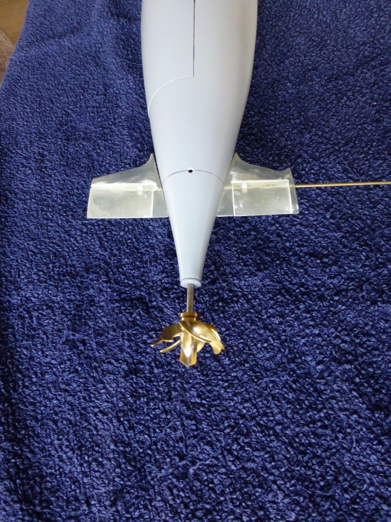
    When I took the planes, rudders and pod and presented them to the hull they seemed out of scale. I remembered that I drew them myself taking pictures as a reference as the shapes of the parts on the Greg Sharpe drawing differed from the pictures. Now they look to big. I shortened (halve an inch) and narrowed them down (1/4 inch) to match the scale.

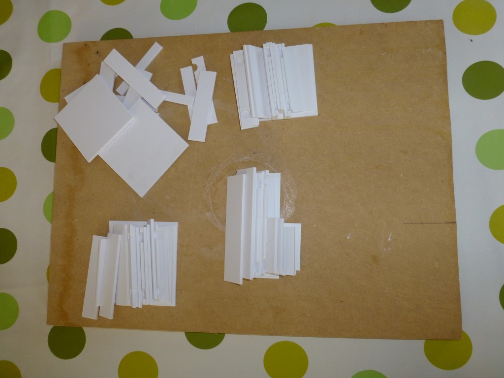
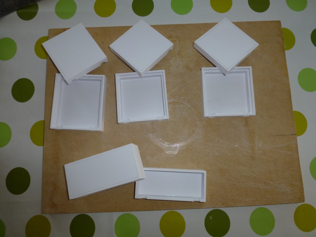
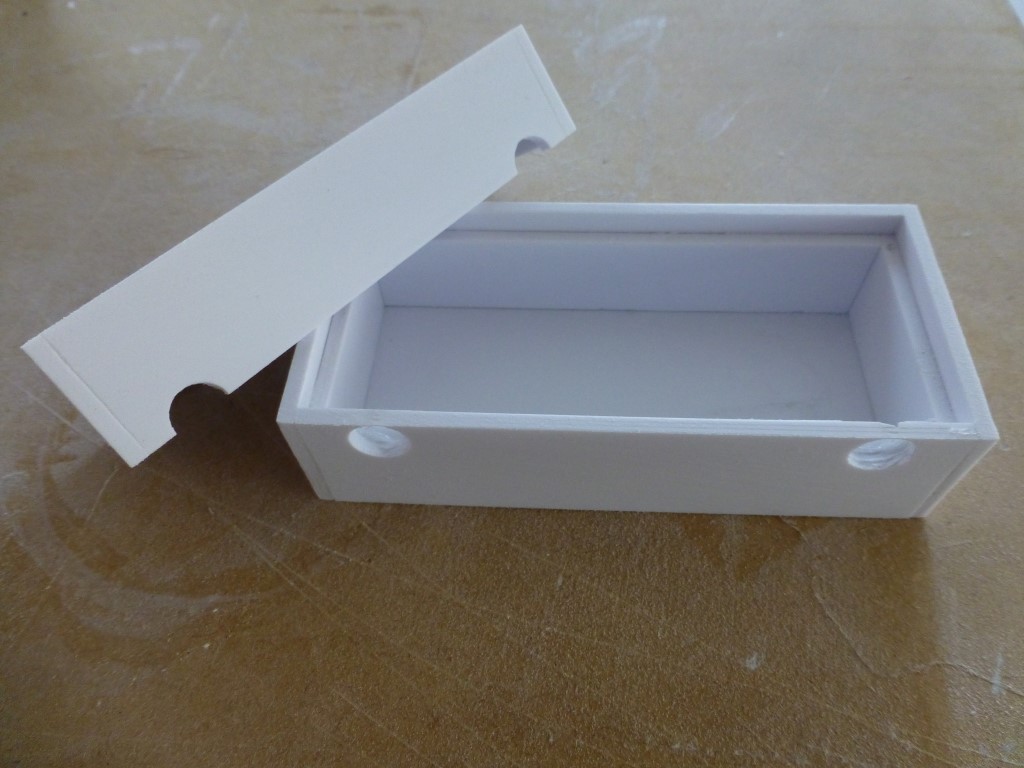
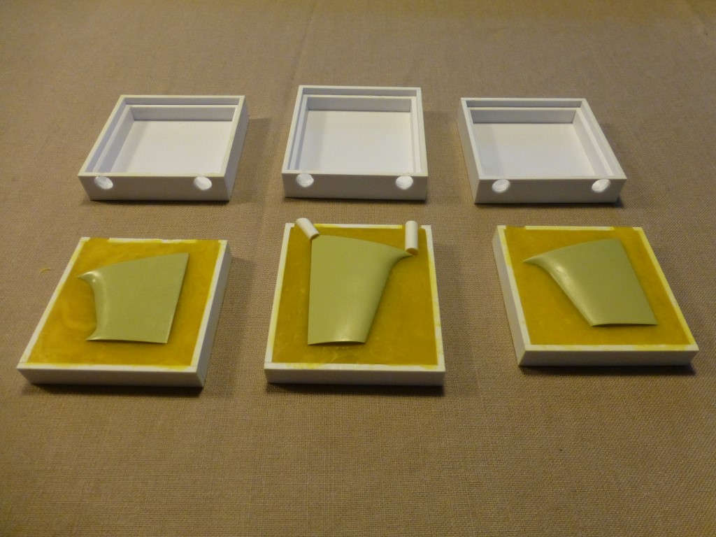
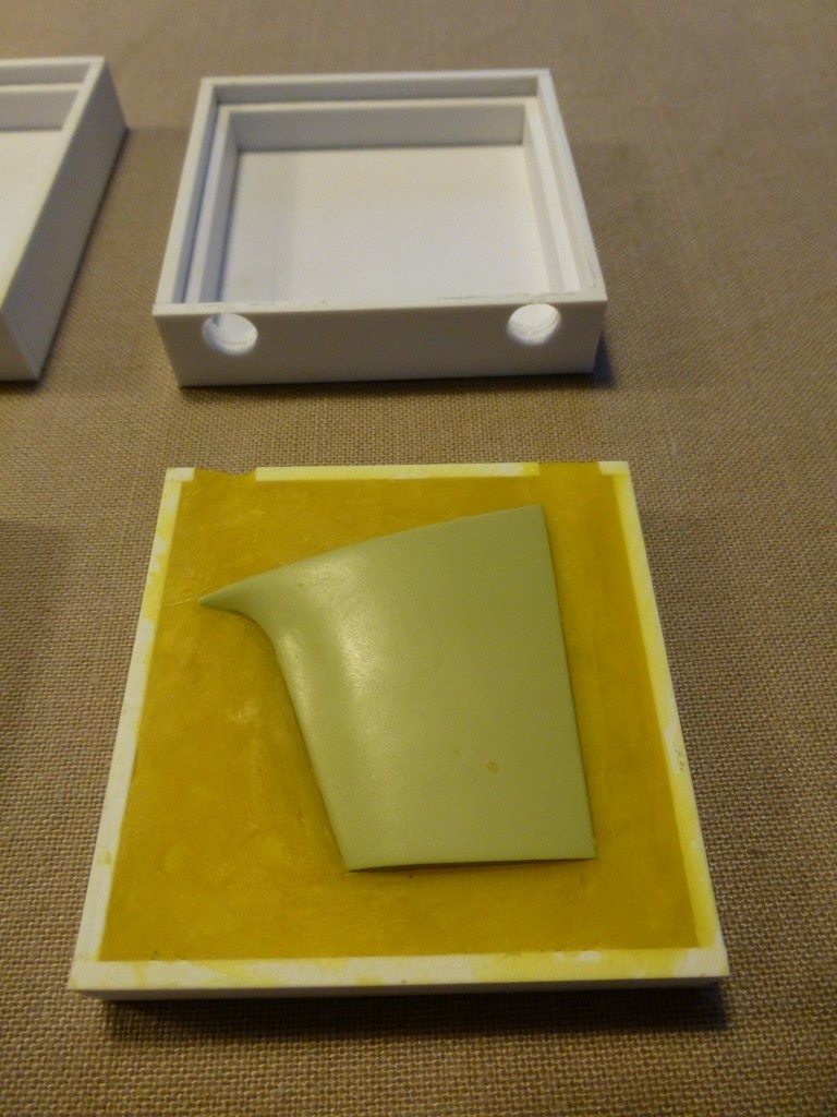
    As the silicone is quite expensive I did not want to waste it in oversize boxes so I tailor-made some boxes out of styrene. The dimensions are slightly larger than the dimensions of the part to cast. The top of the lower part of the box is also the dividing line of the part. It makes it easier to remove the modeling clay excess when you press the part in it. The boxes are provided with two holes for respectively the vent and pouring channel. The lid slides over the lower part.

    Akula 1/144 scratch build Akula_107

    Akula 1/144 scratch build Akula_108

    Akula 1/144 scratch build Akula_109

    Akula 1/144 scratch build Akula_110

    Akula 1/144 scratch build Akula_111

    For the rudder and dive planes this will be an intermediate casting. I have made both out of oak and I’m feel not comfortable to saw the control surface out of the masters, I’m afraid the trailing edges will brake (they are quite thin). So I will first make a cast out of the masters and then saw the control faces out of the cast (if I screw up I only have to cast a new one). Afterwards I will make another cast of the finished pieces.

    A drill press was missing on my machinery list, and this was an item I needed for manufacturing the rudders and diveplanes. I did not need a big machine but I wanted one with high precision. After streaming the WWW I found one for my budget I wanted to spent with a max clearance of 0.02mm on the spindle.

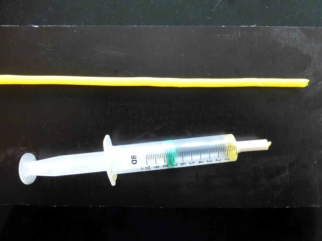
    For the making of the sprue channels I modified a syringe so I got the desired diameter for the channels. Filled the syringe with molding clay an out came the channel.

    Akula 1/144 scratch build Akula_114

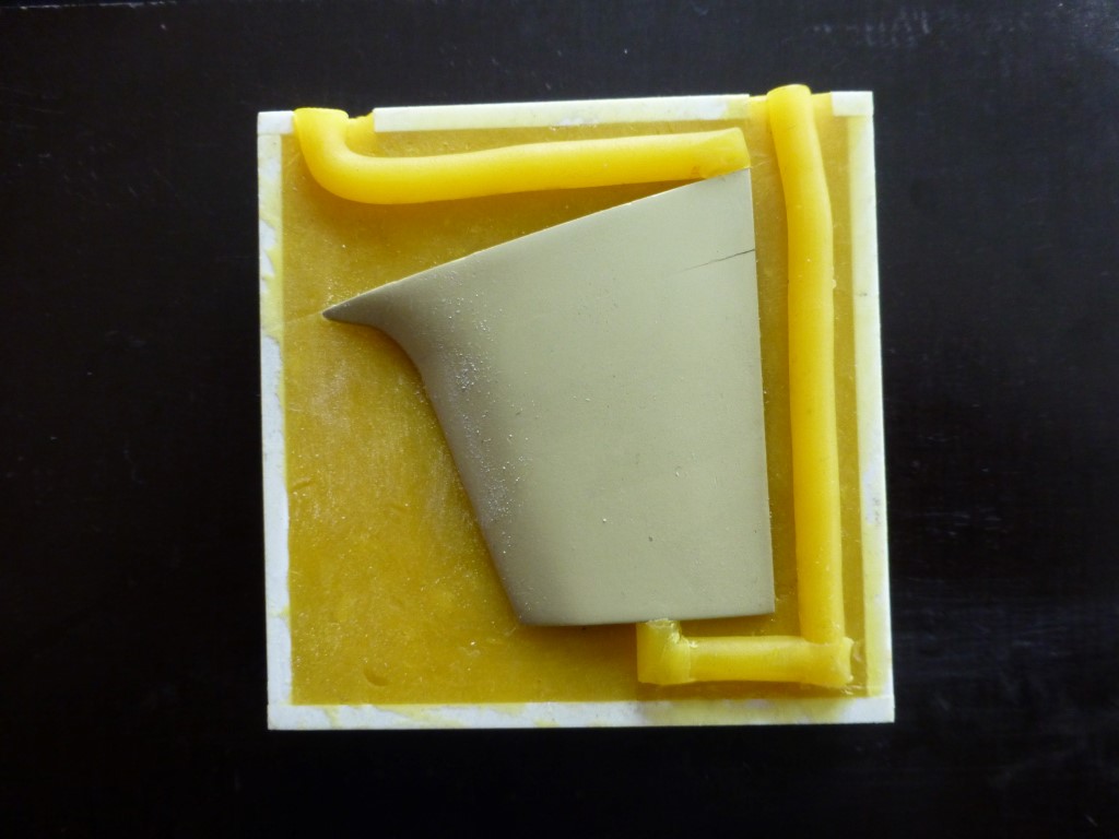
    I cut the cylindrical formed clay in half longitudinally and pressed them in place on the mold.

    Akula 1/144 scratch build Akula_115

    Akula 1/144 scratch build Akula_116

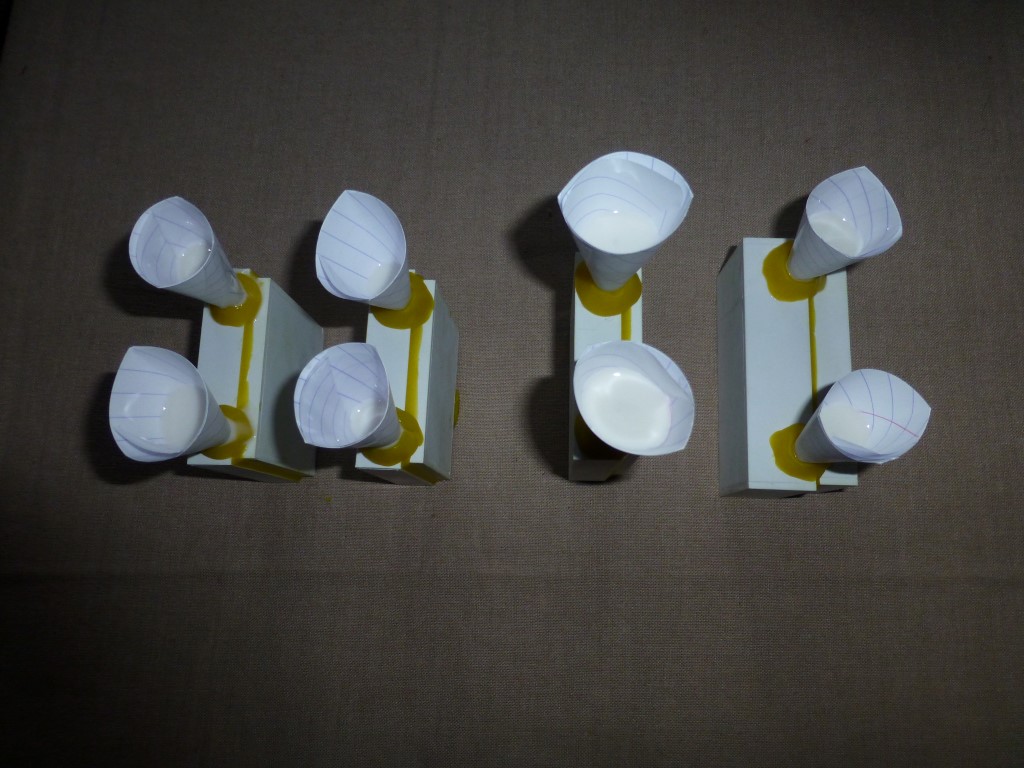
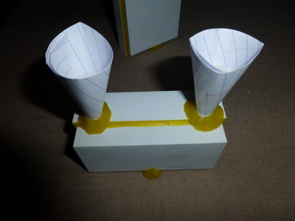
    The mold were closed and the seams were sealed with modeling clay. The poor funnels I made out of paper, put in place and sealed with molding clay. The silicone was degassed in my DYI vacuum chamber (works Great!) and poured into the molds.

    Akula 1/144 scratch build Akula_117

    Akula 1/144 scratch build Akula_120

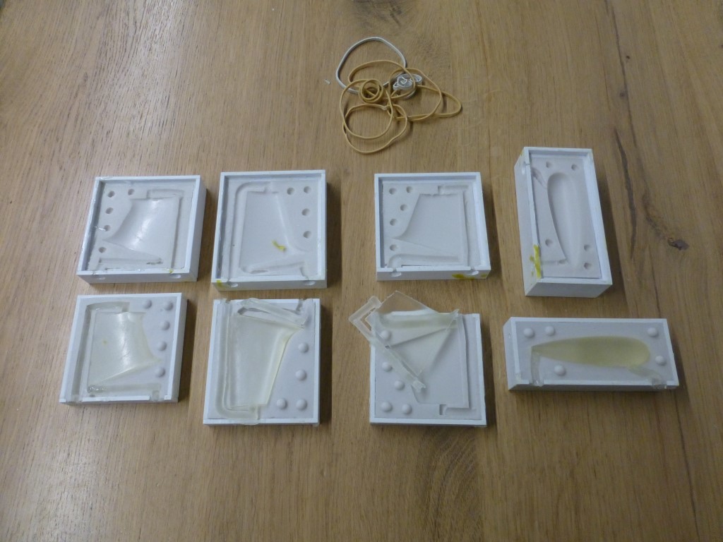
    After curing molds were opened up and master and moulding clay was removed. The only thing I needed to do before pouring the other half is making new sprue channels in modeling clay and put them in place together with the masters……and apply release agent. Closed and sealed everything and poured the other halve. The mold worked out fine.

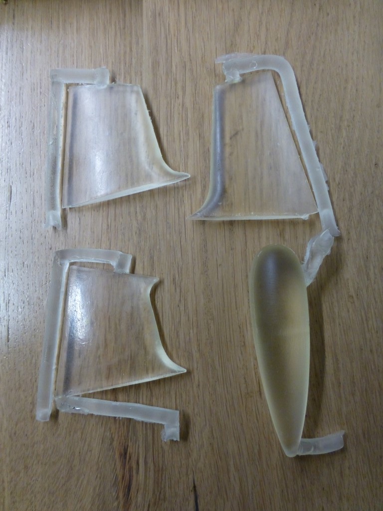
    Next step is to pour the resin in the molds, again I made the pour funnels out of paper. After the molds were filled I placed the in my pressure chamber @ 3bar, and let them cure overnight.  I was very pleased with the result.

    Akula 1/144 scratch build Akula_123

    Akula 1/144 scratch build Akula_124

    Akula 1/144 scratch build Akula_126

    Akula 1/144 scratch build Akula_125

    The only thing I noticed is that the diving plane was slightly bent but the master was straight. I thought I applied to much force when I pressed the master in the modeling clay as the rudder is long and thin it is fragile. Later I discovered that the rudder didn’t fit into the mold anymore. So the mold was OK the deformation happened when I removed the dive plane from the mold. It seems that the resin was not completely hardened. So a casted another one, left it for three days in the pressure chamber and came out perfectly.

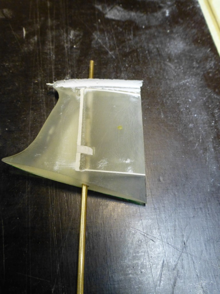
    Next step was to cut the control faces out. Everything was marked in pencil. On the real sub all the rudders and diving planes are provided with trim surfaces these are supported by pintle bearings. I want to integrate these bearing in the model. So these were also drawn.

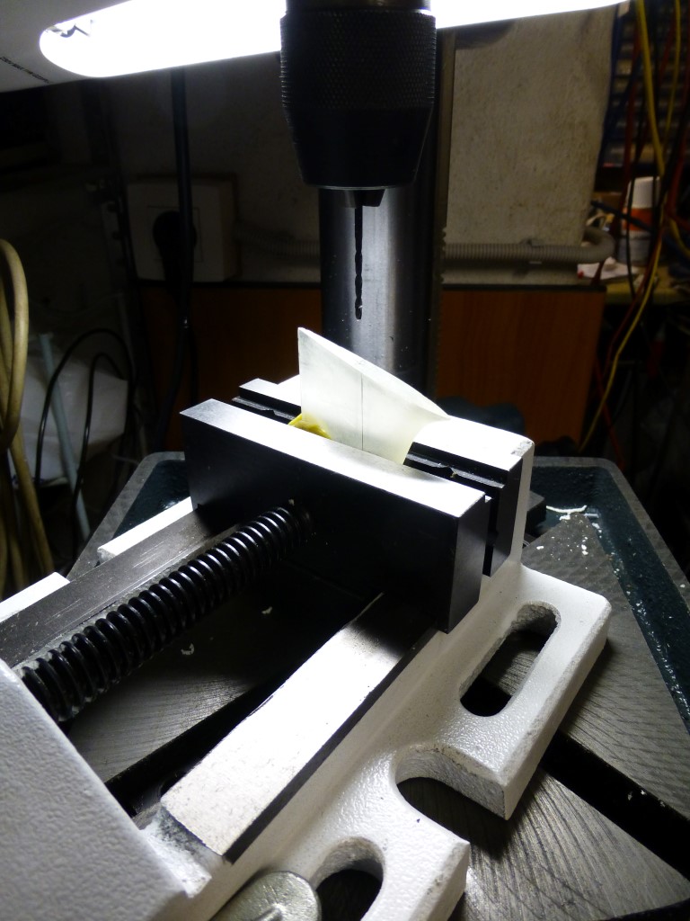
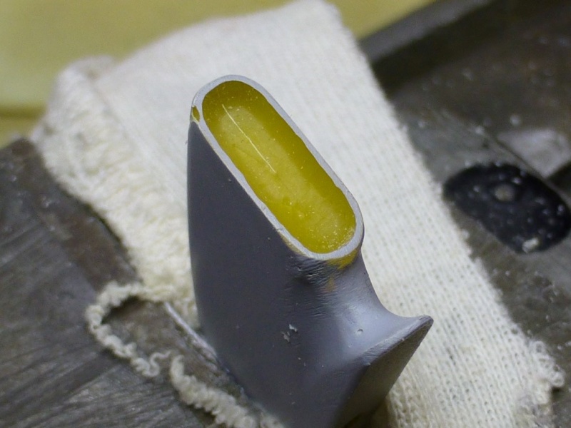
    First I had to drill the rudderstock holes (drill press time). As the rudders and dive planes are double curved it is hard to clamp them in a machine vice without a sort of jig. As I had a lazy day I din’t want to make a jig, so I tried……….modeling clay. This works great, just put an piece of modeling clay on both sided and clamp it in the machine vice, the modeling clay squeezes itself in place wen pressure is applied. 2mm holes were drilled.

    The yellow stuff is the molding clay
    Akula 1/144 scratch build Akula_133

    Akula 1/144 scratch build Akula_134

    The surfaces were cut out with a scroll saw. Before I made the cut I had to level the planes in both directions in order to get a nice vertical cut. This was done with modeling clay. A recess for the pintel bearing was also cut in the control surface. All cut surface were sanded. A radius was sanded on the leading edge of the control surface.

    Akula 1/144 scratch build Akula_135

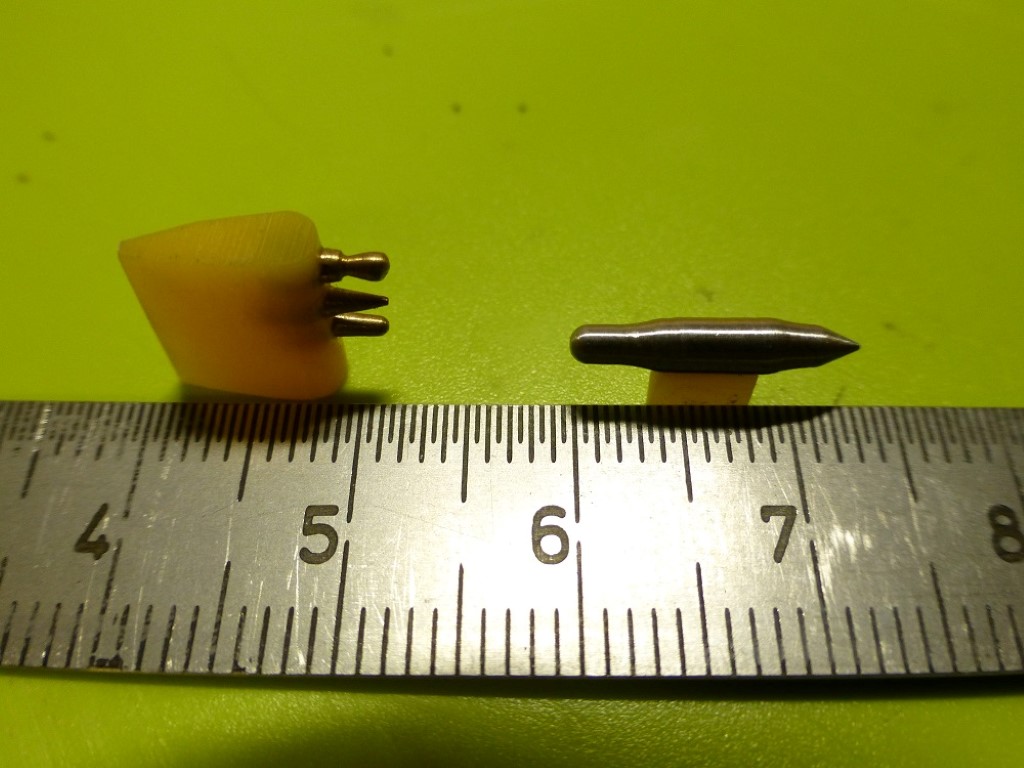
    The pintle bearings (3x5x5mm) were made out of a 3mm styrene sheet glued in place and provided with a 2mm hole.
    The gaps between the control surface and the actual plane were filed up with the EUREKA putty but not before I thickened up the leading edge of the control surfaces by masking tape (4 layers approx. 0,5mm) and applied some release agent so the EUREKA putty will not bond with the tape.

    pintle bearing in place and tape applied
    Akula 1/144 scratch build Akula_128

    EUREKA putty applied
    Akula 1/144 scratch build Akula_137

    Control surface removed
    Akula 1/144 scratch build Akula_138

    After curing all were sanded in shape resulting in a nice small 0,5mm gap. The upper and lower gap between the control surface and plane needed also attention. EUREKA putty was applied on top and bottom and after curing sanded in shape resulting in a nice small gap.

    Akula 1/144 scratch build Akula_140

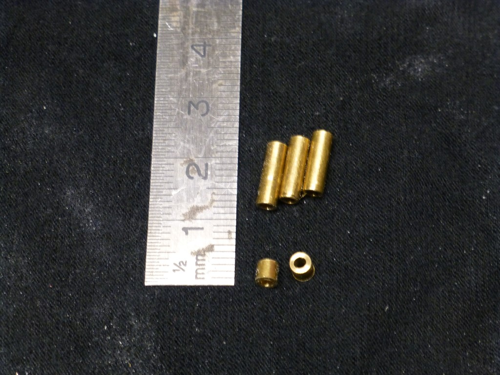
    Bushings will support the rudderstock, I made them out of a 3mm brass rod, the all received a 2mm hole.
    • 4pc for the pintle bearings (rudderstock runs through it) Ø3x3mm
    • 4pc for the upper bearing (protrusion of the hull) Ø3x10mm
    • 3pc for the lower bearing Ø3x3mm

    These bushings will be placed in position in the molds prior to the casting process so they will be imbedded in the parts after casting.

    Akula 1/144 scratch build Akula_142

    Next step was to lineup the rudders and planes to the hull and adapt the roots to the hull for a perfect fit. A release agent was applied on the hull iwo the planes location; EUREKA putty was used to make the curved transition between the hull and planes.

    Upper and lower rudder
    Akula 1/144 scratch build Akula_149

    root adaption upper rudder with towed array pot
    Akula 1/144 scratch build Akula_150

    Rudder removed
    Akula 1/144 scratch build Akula_152

    All rudders and planes were sprayed with automotive primer and sanded in preparation to the molding.
    I would have repeated this process several times but at that moment the winter kicked in and the temperatures in the basement dropped. As my family members voted “against” moving the paint process into the living room I had to find something else to do.

    grtz,
    Bart
    bwi
    bwi
    AMS member


    Posts : 81
    Join date : 2015-01-17
    Location : Belgium

    Akula 1/144 scratch build Empty WTC and Dive module

    Post  bwi Sun Jan 18, 2015 4:26 pm

    WTC and Dive module

    Due to wintertime I focused on the internals of the sub. Me, myself and I quickly agreed that DIY was the way we wanted to go. As usual the others left the building and I remained to figure out “how to”. I had to do some drawing as I also wanted to DIY the piston tank.

    I took possession over the laptop and searched the www for some free 3D drawing software. But I didn't really find something that made me say eureka.
    A former colleague used sketchup to design his house. I previous used it to draw some simple things but something complicated as this I have never done. Nevertheless I had a go at it. After I conquered the basics the software was very kind to me (Normally software and myself don’t get along). They have also great tutorials so I quickly (I thought It was quick.....probably it wasn't) learned the tricks of the trade.

    I spent a lot of time searching for the dimensions of all the necessary gears, bearings and spindles. Also I spent a lot of attention to calculate the necessary dimensions of the components needed (endcaps, o-ring groves, wall thickness, discharge opening,……). For this I found a lot of information in a booklet of Norbert Brüggen and for the o-ring groves I again used the guidlines of Andrew Lawrence.

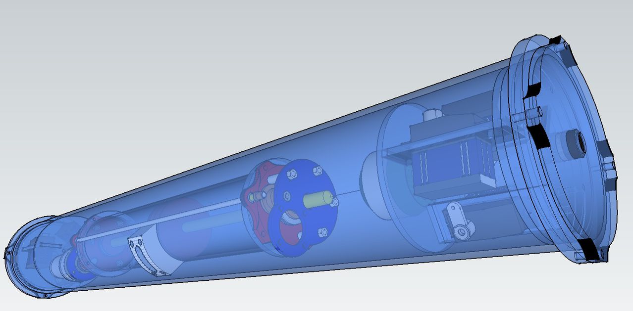
    During the process of drawing all the components I decided I wanted one tank with two piston, both pistons working on one motor. When using a single piston tank, there is a weight shift when the piston moves towards the stem or stern, taking water in or pushing water out. So you need to compensate this. As I want to make a static diver I wanted to minimize this shift so I went for the double piston.

    As I want to make a static diver I wanted to minimize this shift so I went for the double acting piston tank.
    I took over the Idea from the webside of Markus Reidegeld he made several of these tanks. Also the positioning of the servo’s I took over from him.

    All this information was transferred to the drawing board. Just one sentence but it took me almost two months to do it but I can now officially state that I have some experience with Sketchup.

    Akula 1/144 scratch build WTC_001

    Akula 1/144 scratch build WTC_002

    Akula 1/144 scratch build WTC_003

    Akula 1/144 scratch build WTC_004

    you will note that there are six servos drawn but that was just to see how much I could squeeze in, the fwd three will be reduced to one piece and the aft three to two pieces.

    The length of the pistontank needs to be adapted to the necessary ballast volume I have to take in. It will be less than the 500ml I have drawn now, so room will be available for the battery.
    The dimension of the WTC is dia 80mm x 550mm [3” x 22”]. The calculated dive time is 5 sec for 500ml.

    grtz,
    Bart
    bwi
    bwi
    AMS member


    Posts : 81
    Join date : 2015-01-17
    Location : Belgium

    Akula 1/144 scratch build Empty As is

    Post  bwi Sun Jan 18, 2015 4:36 pm

    That’s it for now.

    Two years progress posted in two days.
    This is the "as is" state of the sub.
    Next postings will surely come much slower
    Thanks for reading

    Grtz,
    Bart

    Akula 1/144 scratch build Akula_144
    bwi
    bwi
    AMS member


    Posts : 81
    Join date : 2015-01-17
    Location : Belgium

    Akula 1/144 scratch build Empty @ tattooed

    Post  bwi Sun Jan 18, 2015 5:00 pm

    Andy, thank you very much for your nice words.

    Grtz,
    Bart
    avatar
    Dr.Schmidt
    Guest


    Posts : 171
    Join date : 2013-03-20
    Location : Germany, Bavarya

    Akula 1/144 scratch build Empty Re: Akula 1/144 scratch build

    Post  Dr.Schmidt Sun Jan 18, 2015 7:07 pm

    Looks great. Good work...
    merriman
    merriman
    Guest


    Posts : 347
    Join date : 2011-10-16
    Age : 75
    Location : Virginia Beach, Virginia

    Akula 1/144 scratch build Empty Re: Akula 1/144 scratch build

    Post  merriman Sun Jan 18, 2015 9:28 pm

    Well done, sir. And I applaud your effort to credit those who helped inspire and inform your AKULA project. We are all indebted to those who came before us.

    Thoroughly enjoyed your propeller blade assembly fixture and indexing plate. Neat, well engineered, and practical gizmo's on display, sir. You've taken me back to school.

    Can't wait to see this sucker in the water.

    David
    david f
    david f
    AMS Treasurer


    Posts : 2412
    Join date : 2010-11-10
    Age : 74
    Location : Cumbria

    Akula 1/144 scratch build Empty Re: Akula 1/144 scratch build

    Post  david f Thu Jan 22, 2015 3:22 pm

    I have just taken another half hour to read this excellent build log. I can smell the polyester resin as I read it!

    I wonder if you have tried PVA release agent rather than the wax method? (I have tried them both and would not go back to wax. I have also tried them both in combination and that gave big problems with the PVA forming droplets rather than producing a film. I now just use PVA.)

    David
    bwi
    bwi
    AMS member


    Posts : 81
    Join date : 2015-01-17
    Location : Belgium

    Akula 1/144 scratch build Empty @ merriman

    Post  bwi Fri Jan 23, 2015 8:55 am

    I hadn’t seen this one coming…….didn’t know you were still active online.

    Without being a buttshark….your building reports made this happen so I’m very honored with your comments sir.

    I'm too looking fwd to the nerve racking moments thinking “will she popup again.”

    Grtz,
    Bart
    bwi
    bwi
    AMS member


    Posts : 81
    Join date : 2015-01-17
    Location : Belgium

    Akula 1/144 scratch build Empty @ david f

    Post  bwi Fri Jan 23, 2015 9:36 am

    I have used PVA agent in combination with wax without any problem although the PVA gave me some brush marks that I had to polish out maybe spraying it on will solve this.

    Just using PVA agent didn't work for me.....I accidently rubbed the wax off the masters so the only thing left was the PVA agent. When I try to remove the masters some places were glued into the gel coat.

    polyester resin is wonderful stuff .....when I was making the molds for the hulls the soles of both my shoes came off......the vapors dissolved the glue.....I had to glue them back on afterwards.

    grtz,
    bart
    bwi
    bwi
    AMS member


    Posts : 81
    Join date : 2015-01-17
    Location : Belgium

    Akula 1/144 scratch build Empty @ Dr.Schmidt

    Post  bwi Fri Jan 23, 2015 9:55 am

    Thks.....nice work yourself.....I follow your build log also with great interest.

    Grtz,
    bart
    avatar
    Dr.Schmidt
    Guest


    Posts : 171
    Join date : 2013-03-20
    Location : Germany, Bavarya

    Akula 1/144 scratch build Empty Re: Akula 1/144 scratch build

    Post  Dr.Schmidt Fri Jan 23, 2015 10:11 am

    PVA cannot be polished, wax can....
    merriman
    merriman
    Guest


    Posts : 347
    Join date : 2011-10-16
    Age : 75
    Location : Virginia Beach, Virginia

    Akula 1/144 scratch build Empty Re: Akula 1/144 scratch build

    Post  merriman Fri Jan 23, 2015 11:50 am

    bwi wrote:I hadn’t seen this one coming…….didn’t know you were still active online.

    Without being a buttshark….your building reports made this happen so I’m very honored with your comments sir.

    I'm too looking fwd to the nerve racking moments thinking “will she popup again.”

    Grtz,
    Bart
    Still kicking, still on line ... anyway, still on line at those forumes I've yet to get banned from.

    It pleases me no end to hear that my Cabal Reports and other writings have been put to practice by you and others. Others taught me. I teach you. If we don't do that; if we don't keep the Craft alive, the 3D printers and CNC machines win.

    You, Bart, are a Craftsman. You got the torch: run with it!

    David
    bwi
    bwi
    AMS member


    Posts : 81
    Join date : 2015-01-17
    Location : Belgium

    Akula 1/144 scratch build Empty Intake Scoop & SOCKS & Small Parts

    Post  bwi Sun Feb 08, 2015 4:30 pm

    As I’m preparing for molding, some other part needed fabrication. The hatch of the communication buoy is fitted with protection for the cable.

    Akula 1/144 scratch build Akula_12

    The difficult part was the symmetry between PS and SB protection. I started tag-gluing to pieces of 3mm acrylate sheet. Then drew the longitudinal outline on it and grinded it into shape.
     
    Akula 1/144 scratch build Akula_13

    Akula 1/144 scratch build Akula_14

    Akula 1/144 scratch build Akula_15

    Next was the cross section this was also grinded in shape, togeter with my fingernails…..this stuff is small.

    Akula 1/144 scratch build Akula_16

    Akula 1/144 scratch build Akula_17
     
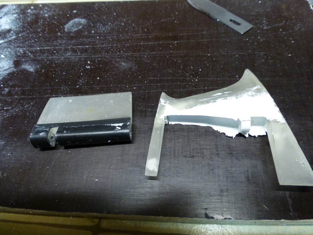
    The parts were separated resulting in 2 symmetrical protections

    Akula 1/144 scratch build Akula_18

    Akula 1/144 scratch build Akula_19
     
    The Fwd escape hatch was also fabricated, I had a picture as an example.

    Akula 1/144 scratch build Akula_20
     
    The dome was made out of 3mm acrylate, the diameter is 13mm.

    Akula 1/144 scratch build Akula_21

    The scoop I initially made was oversized so I narrowed everything down. The inlet was opened up with a handheld grinder.

    Akula 1/144 scratch build Akula_22

    Akula 1/144 scratch build Akula_23
    .
    Now some more spraying and sanding and she will be ready for molding.
    bwi
    bwi
    AMS member


    Posts : 81
    Join date : 2015-01-17
    Location : Belgium

    Akula 1/144 scratch build Empty Rudders, Planes & Towed array pot

    Post  bwi Sun Feb 08, 2015 4:55 pm

    I managed to spray and sand the parts several times and their ready for molding.

    Akula 1/144 scratch build Akula_24

    Akula 1/144 scratch build Akula_32

    Initially I didn’t wanted to make use of the Fwd planes, but along the way I have decided to use them for depth control. So I had to fabricate them, they will be fixed not retractable. As previous mentioned I first chapped my rudders and planes an afterwards, when I bought a drill press, I drilled the holes for the rudderstock. It was not so evident to get the hole nicely in the centerline.
    So I decided to drill the hole of the rudderstock first and then shape the Fwd plane.
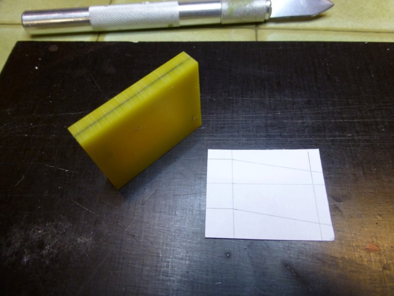
    I started with two pieces of 3mm of acrylate sheet, cut at the right dimensions and clued together. Then I draw the longitudinal section on a piece of paper, inclusive the position of the hole for the rudderstock, and glued it on the workpiece.

    Akula 1/144 scratch build Akula_25

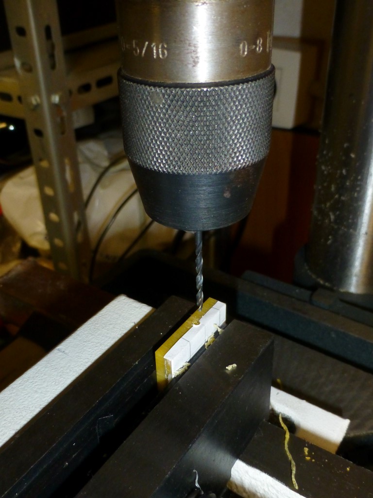
    The workpiece was clamped into the machine vice an de 2mm hole was drilled, as the shape was rectangular and flat it was a piece of cake to drill the hole in the centerline. Next the piece was cut to the longitudinal outlines.

    Akula 1/144 scratch build Akula_26

    Akula 1/144 scratch build Akula_27
     
    Then I drew the cross-sections of the plane on paper and clued them to the workpiece, and grinded/sanded into shape.

    Akula 1/144 scratch build Akula_28

    Akula 1/144 scratch build Akula_29

    Akula 1/144 scratch build Akula_30

    Akula 1/144 scratch build Akula_31

    That's it for now,
    Grtz,
    Bart
    bwi
    bwi
    AMS member


    Posts : 81
    Join date : 2015-01-17
    Location : Belgium

    Akula 1/144 scratch build Empty Scribing

    Post  bwi Mon Mar 09, 2015 8:34 pm

    I postponed this one for a long time, kept pushing it fwd. But I have to do it sooner or later. I never have done this but there were plenty thing I had never done before this build, fail and error, fail and error.

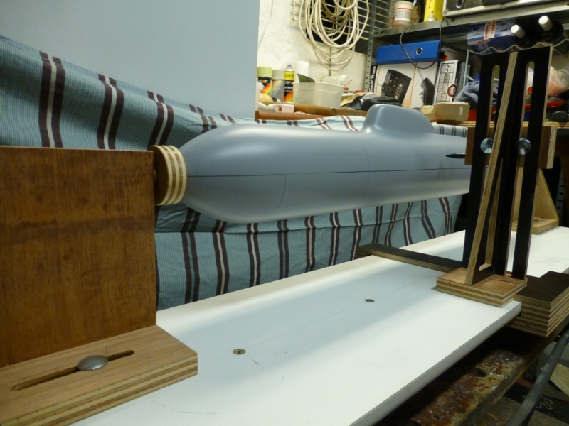
    In preparation to the scribing I have to draw every single hatch, hole,….onto the hull. I have seen this done by David Merriman, he made some kind of jig that holds the boat and it enables it to turn around freely, it works like a lathe.

    Making all these jigs is time consuming so when I do it I use good solid materials so I can reuse them for later projects.

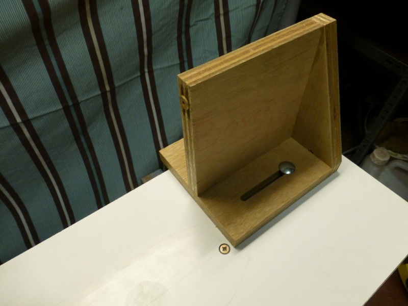
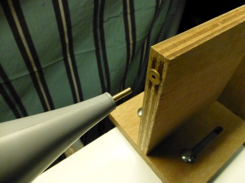
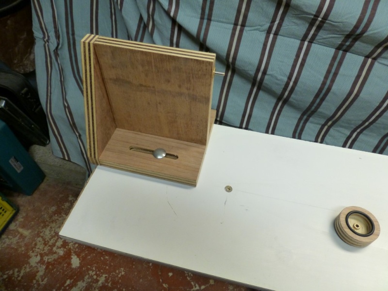
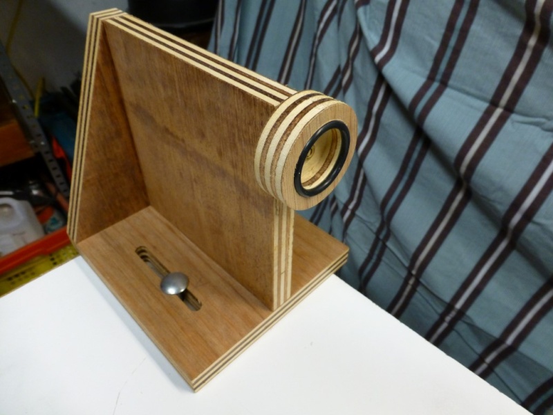
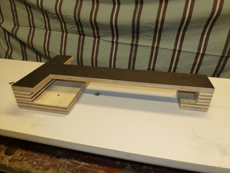
    The molding board that I made previous was used as the base structure. On top two post were placed. The post have some horizontal travel so the hull can be placed in-between, this was managed with a slotted baseplate. I have designed the base of the post in such way that they do not protrude the  perpendiculars of the hull, else the would get in the way when drawing.

    Akula 1/144 scratch build Akula_33

    The sterntube is used to connect the stern to the aft post by means of a 4mm diameter shaft, the aft post is provided with a bushing (inner diameter 4mm outer 8mm with collar).

    Akula 1/144 scratch build Akula_34

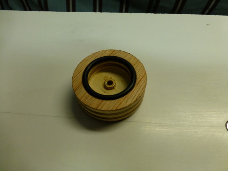
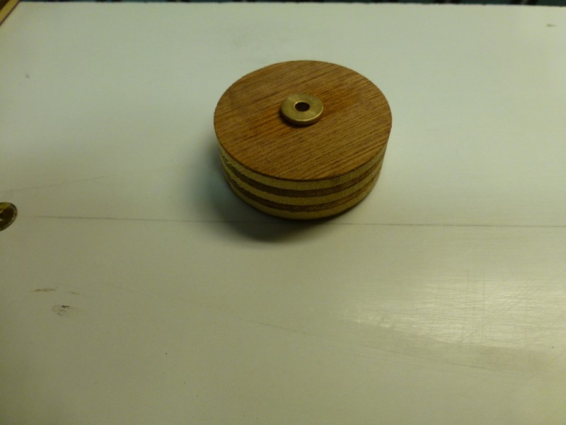
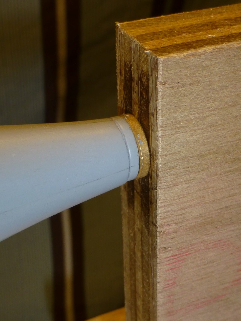
    As I didn’t want to drill a hole in the bow I came up with a hollow disk that would take the curved bow. I provided the disk with an o-ring in order to get enough friction between the disk and the bow. The disk is also be provided with a bushing, and same goes for the  Fwd post. A dia 4mm rod is connecting the disk with the post.

    Akula 1/144 scratch build Akula_35

    Akula 1/144 scratch build Akula_36

    Akula 1/144 scratch build Akula_37

    Akula 1/144 scratch build Akula_38

    All the a.m. part were fabricated and installed to the molding board. The hull was presented to the jig and it turned out very well, no hiccups.

    In order to get a nice perpendicular movement from the marker with the hull I also fabricated a movable guide/ruler that can be tighten to the base (moulding board).

    Akula 1/144 scratch build Akula_39

    Akula 1/144 scratch build Akula_40

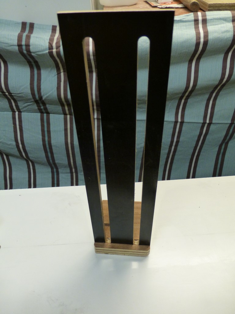
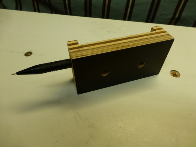
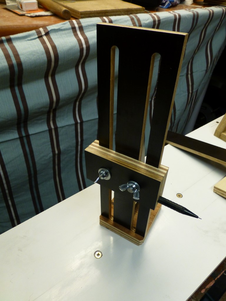
    As I finished that I also made the post that retained the marker, the post is also provided with slots for the up and down movement. I designed in such way that the point of the marker is in aligned with the edge of the ruler.

    Akula 1/144 scratch build Akula_41

    Akula 1/144 scratch build Akula_42

    Akula 1/144 scratch build Akula_43

    Akula 1/144 scratch build Akula_44

    Akula 1/144 scratch build Akula_45

    Some pictures from the whole.

    Akula 1/144 scratch build Akula_46

    Akula 1/144 scratch build Akula_47

    Akula 1/144 scratch build Akula_48

    Detail of the fwd and aft connections to the posts

    Akula 1/144 scratch build Akula_49

    Akula 1/144 scratch build Akula_50

    Now I have run out of  things to fabricate so the only thing left now is to mark everything, d*mn I realy like to design these things.

    Grtz,
    Bart
    bwi
    bwi
    AMS member


    Posts : 81
    Join date : 2015-01-17
    Location : Belgium

    Akula 1/144 scratch build Empty WTC and Dive module (continued)

    Post  bwi Sat May 16, 2015 1:52 pm

    My initial idea of the pistontank looked nice on paper but:

    I ordered all the necessary parts. The plexiglass (PMMA) arrived diameter 80mm for the WTC and 50mm for the Pistontank.

    As I needed max length (piston tank spindle) the WTC was cut at the max length the boat could take 670mm instead of the initially 550mm. When presented in the boat there was no space to add foam or any other stuff. When I weighted the hull and WTC and calculated the bouncy (with the estimated weights of all bit and pieces) I came to the stunning conclusion the she would sink, there was nothing left and I had no space left to add foam. But I needed the length for the spindles of the piston tank.

    I hit the brick wall hard and was lying on the floor. It was time to reconfigure the ballast system.

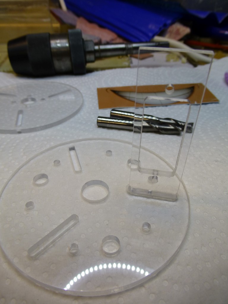
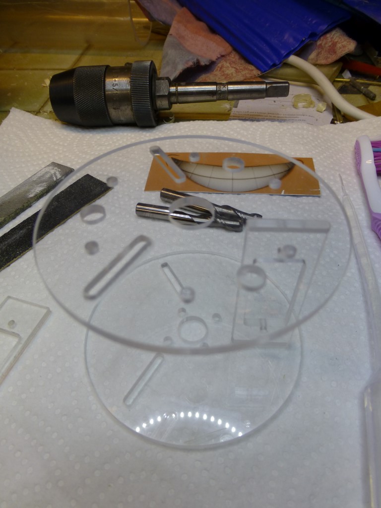
    Still pondering about the ballast system but I focused to the fabrication of the endcaps. As I only have a small lath I decided to cut disks out of 4mm thick plexiglass. I did the same for the lit for vacuum tank, and it worked well. You just have to cut one disc smaller in diameter to take the O-ring. Glue everything together and you have a perfect endcap without using a lath.

    Akula 1/144 scratch build Akula_11

    Akula 1/144 scratch build Akula_12

    Akula 1/144 scratch build Akula_13

    Akula 1/144 scratch build Akula_14

    I have spent quite some time in designing the end caps. Holes for the pushrods and prop shaft are integrated also the alignment for the servos took all of my attention.

    Akula 1/144 scratch build Akula_15

    Akula 1/144 scratch build Akula_16

    Akula 1/144 scratch build Akula_18

    Akula 1/144 scratch build Akula_17

    Akula 1/144 scratch build Akula_19

    Akula 1/144 scratch build Akula_20

    I have provided 2 prop shaft seals and two bearings I was a chief engineer.on merchant ships so I like redundancy (No Hardware stores @ sea).

    Akula 1/144 scratch build Akula_24

    Akula 1/144 scratch build Akula_25

    Akula 1/144 scratch build Akula_26

    Akula 1/144 scratch build Akula_27

    Take in mind that drilling holes in plexiglass can be tricky. The drill jammed..... &#%!@?!…...so I had to start all over. Message to myself. DRILL THE HOLES BEFORE YOU GLUE EVERYTHING TOGETHER YOU IDIOT; THAT ARE 4 FT WORKING DAYS (I forgot to make the holes for the wires).

    Akula 1/144 scratch build Akula_21

    Akula 1/144 scratch build Akula_22

    Akula 1/144 scratch build Akula_23

    I had 6mm holes foreseen where the pushrods protruded the WTC as I couldn’t decide what sealing system I wanted to use. A bellow seems the easiest, but they are fragile and can’t cope with pressure very well, I had to take that into account as I still haven’t made up my mind on the ballast system.

    O-rings was the way to go, so I designed a stuffing box, It had to be replaceable. I needed O-rings outside to make the seal with the WTC and inside to make the seal with the pushrod. I have some redundancy build in, two o-rings each. The pushrod will be 1,5mm in diameter.

    Here again I used the electronic drawing board. As everything is gonna be so small I had to make it out of 4 sections as it would be impossible to put the inner o-rings in place true the 2mm hole that takes the pushrod.

    Akula 1/144 scratch build Pr10

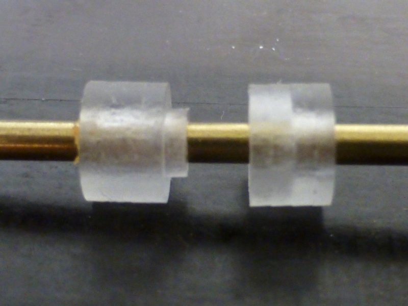
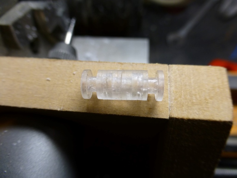
    Time for the prototype. I made the 4 sections separately out of 5mm plexiglass. Why on earth in plexiglass because you can glue it with acetone. And acetone hasn’t any effect on the O-ring (and I had some leftovers). That way I could position the inner O-ring (still on backorder, so it not shown) then glued everything together.What I did as it is a prototype. Stuffing box dimensions outer diameter is 5,9 something, length 15mm.

    Akula 1/144 scratch build Akula_28

    Akula 1/144 scratch build Akula_29

    Akula 1/144 scratch build Akula_30

    Akula 1/144 scratch build Akula_31

    Akula 1/144 scratch build Akula_32

    I was pondering how to provide the outer groves. The trouble was it hat to be precise and I could not put to much strength on the stuffing box. The bore is 2 mm in diameter and the inner diameter of the grove would be 3,1mm; 0.5mm material remained (0.02 inch).

    I came up with this. I use a hand grinder.  I made a jig to support my hand grinder. The tool holder of the lath was replaced by this jig. A 1mm diameter cutter was installed in the grinder. The grove dimensions are diameter 3,2mm, wide 1.8mm.

    Akula 1/144 scratch build Akula_33

    Akula 1/144 scratch build Akula_34

    Akula 1/144 scratch build Akula_35

    Akula 1/144 scratch build Akula_36

    Akula 1/144 scratch build Akula_37

    Akula 1/144 scratch build Akula_38

    Akula 1/144 scratch build Akula_39

    Akula 1/144 scratch build Akula_42

    The O-rings were installed and the seal assembly was test fitted in the WTC. Nice tight fit. Mission accomplished. When I receive the inner o-rings I will start production of the 4 stuffing boxes.

    Akula 1/144 scratch build Akula_40

    Akula 1/144 scratch build Akula_41

    Grtz,
    Bart
    david f
    david f
    AMS Treasurer


    Posts : 2412
    Join date : 2010-11-10
    Age : 74
    Location : Cumbria

    Akula 1/144 scratch build Empty Re: Akula 1/144 scratch build

    Post  david f Mon May 18, 2015 11:16 am
    Lovely work Bart!

    I was interested to hear about your conclusion that the sub could not float.

    This happens - I believe it happened to a 1:1 Spanish sub recently!

    With small subs you can easily run out of buoyancy. I think that can justify a dry-hull concept rather than a WTC.

    I was impressed by your use of plexiglass (perspex). I found that the darned stuff used to fracture too much and so I started using polycarbonate. Do you use a particular grade or mix of plexiglass perhaps?

    David

      Current date/time is Wed Oct 30, 2024 10:52 am