The internet; small, relatively cheap camcorders; the ease and facility to edit and store recorded scenes. All have given us the ability to video record our activities at the boating site. Yet few of us do because of the hassle involved in getting someone to handle the camcorder, and be trusted to get the scenes recorded the way we want; and its awkward to keep turning our attention away from the water to give direction to the camera operator. So those great shots of our model submarine surfacing, submerging and stoutly making the local watering hole safe for democracy/communism/ the national socialists party/the Emperor/the peoples republic, etc. Just does not get done. An individual simply can't handle the transmitter AND a camcorder at the same time and do either task well.
But, wait! What's that in our hands.? Yes!, it's a transmitter!
Well, moron, why not make that transmitter useful and affix to it a specialized camera mount?
Simply attach the camcorder to the transmitter with a dedicated camera mount and you've eliminated the camera-man. This way you point the camera where you want it, and its large flat-screen view-finder permits you to orient the transmitter so the video being recorded is framed correctly.
The trick is devising the camcorder-transmitter interface mount. And that's what I'm presenting here: a special camera mount with bracket that attaches to the transmitters carrying handle; an interface mechanism between transmitter and camcorder.
( If your transmitter does not have a handle, then a little re-design will produce a camera mount that screws directly to the transmitter case. Just make sure there are no circuit boards or other vital organs within the area being worked that would be damaged as your drill and tap holes atop the transmitter case).
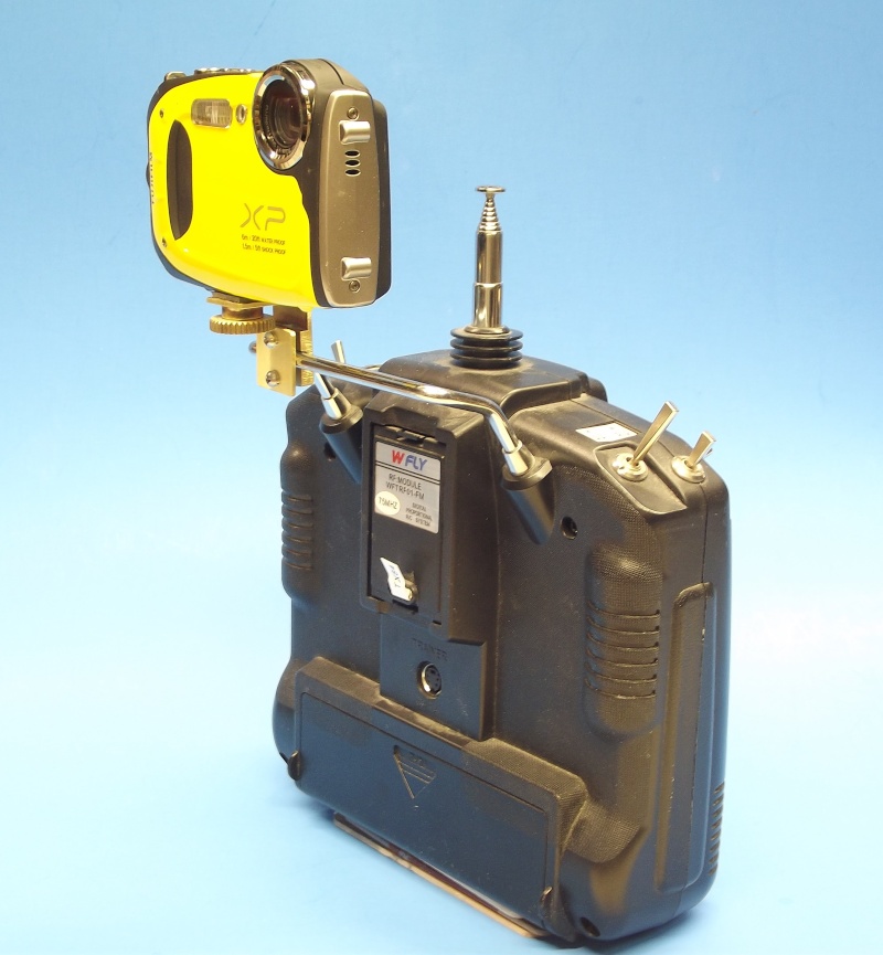
As you can see here -- if your transmitter has a carrying handle -- it's a rather straightforward process to devise a camera mount that will hang off of it. So oriented, the camera view-screen is in the direct line-of-sight of the operator, and also sits clear of the transmitters antenna.
My version of the camera mount permits both pan, tilt and transverse adjustments. This ability situates the camera so it's aimed at the image you want captures, yet permits a comfortable orientation of the transmitter, suited to your normal operational posture.
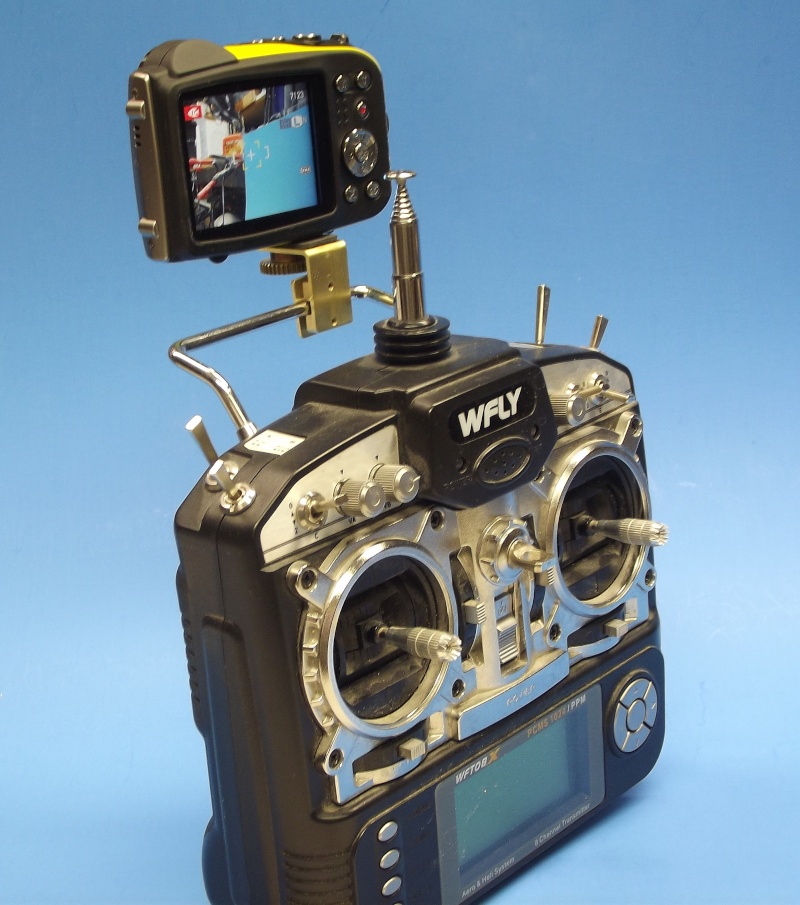
The camera mount can be slide horizontally on the handle so that your view of the view-finder screen and access to the cameras controls is unobstructed by the transmitters antenna. Today's cameras, with their big and bright view-finder displays make easy the task of holding the subject in frame -- even with the camera a good foot-and-a-half away from your eyes -- as you control the submarine model from the transmitter.
A word of caution: splitting your attention between transmitter and camera is fine for relatively slow submarines, but not at all recommend for model aircraft or fast boats and cars. You wouldn't text-and-drive.
Don't video-and-fly!
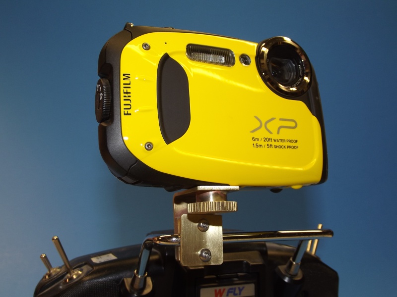
This makes clear how the camcorder mount is secured to the horizontal leg of the transmitter handle. The serrated thumb-screw started life as a length of brass pinion gear 'wire' I had left over from a job. The gear teeth making the perfect high-friction perimeter of the thumb-screw used to hold the camcorder down tight on the mount. The stock was chucked up in the lathe, the end of the pinion stocked faced, and bored, and tapped with a 1/4-20 thread. I then parted off two 1/4" wide pieces and later glued short lengths of 1/4-20 stainless-steel all-thread to each thumb-screw wheel (I made two camera-to-transmitter mounts).
The tilt angle of the camcorder to the transmitter is changed by loosening one of the bracket screws, pitching the mount to the desired angle, and retightening the bracket screw. Pan angle is set with the mounts thumb-screw: Loosen it, yaw the camera in the direction desired, then re-tighten the thumb-screw.
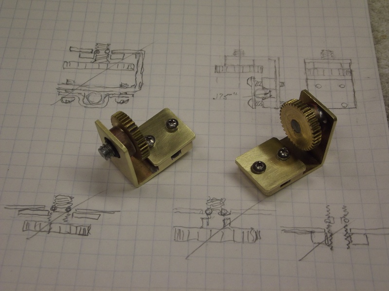
In this Illustrated you see the rejected concept sketches below and to the left of the accepted design. All on paper, before the first piece of brass stock was pulled off the rack. Make things evolve in your head, not the work-bench ... or you wind up with a Rube Goldberg monstrosity!
When coming up with a gizmo like this camera mount, things start off as a brain-storm over breakfast; takes mental form during my hideous morning walk; and the ... wait for it ... eureka! moment hits me in the bathroom; I then rush to the shop (invariably, a piece of toilet paper trailing behind me), break out the graph-paper and start doodling orthographic projections before the idea has a chance to evaporate.
One version ... nope, too complex. Next version ... nope, to damned weak. Each new study -- now in two-dimensional form -- staring accusingly back at me from the graph-paper. Each study an attempt to simplify and enhance the function of the proposed device. On and on, till the thing starts making good sense.
Then one final doodle: This one in isometric to capture in one drawing both height, width, and depth -- a good way to identify interference problems and any paradox between plan and profile views. A good check before starting the actual work.
To the metal stock rack. Is the stuff I need on hand to do the job? If need be the drawing is modified to suite what I have on hand. The materials identified on hand I set to work. Machine brass for the parts to be milled and turned; cartridge brass for those items that will be sawed and bent. Both alloys easy to solder, and look snazzy when polished out. Perfect.
"TO THE BAT-CAVE!"
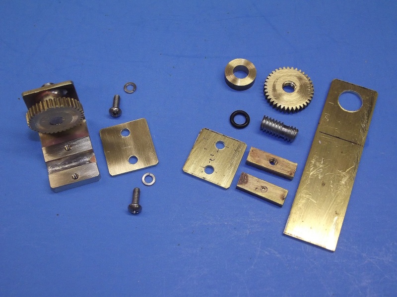
An assembled and ready to use camcorder mount to the left. The parts for another camcorder mount to the right.
Note how a bracket plate is screwed down over the transmitter handle to make fast the mount to the transmitter. The camcorder mount can be removed or installed in less than a minute. Tilt angle is adjusted by loosening the bracket screws, positioning the camera mount, and re-tightening the bracket screws -- an adjustment to suit the unique transmitter handling style of the operator.
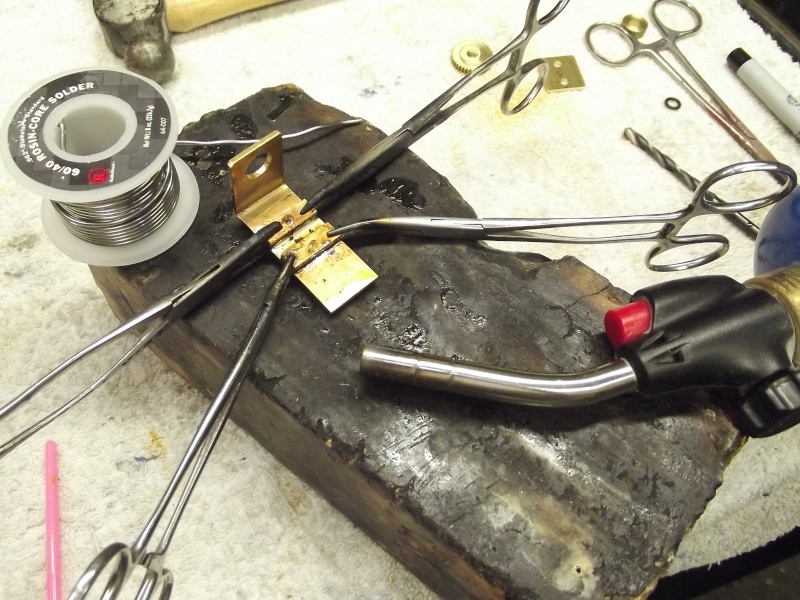
The majority of the camera mount components were assembled with soft solder.
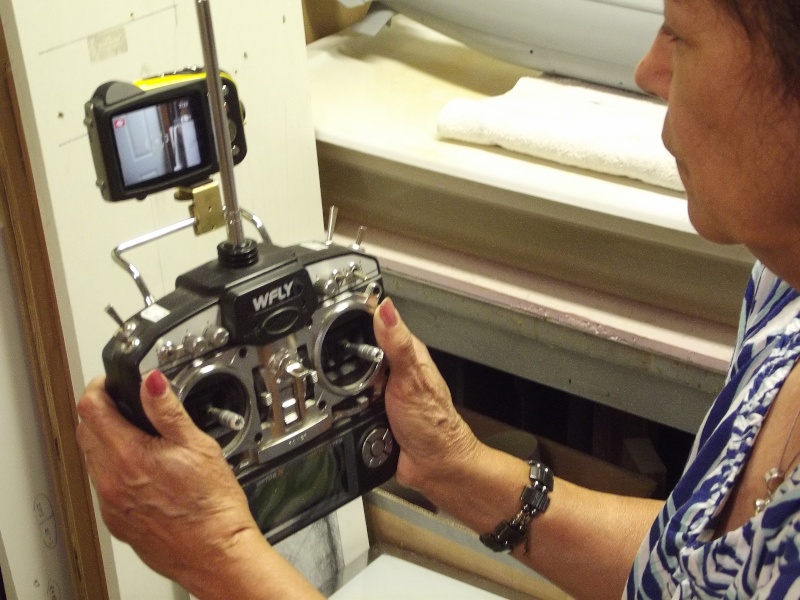
Ellie's demonstrating how the camcorders big view-finder is easily seen as the transmitter is used to both control the r/c model submarine and serve as a base for the camcorder.
As your eyes are focused on the submarine on or under the water, a quick glance every now and then at the camcorder screen tells you where to point the transmitter to keep the action centered where you want it. Also, the mass of the transmitter is an aid in that it helps damp out operator induced shaking that would otherwise spoil the shot.
Here's a YouTube video taken with a transmitter mounted camcorder:
https://youtu.be/meh-QwA2fYE
David
But, wait! What's that in our hands.? Yes!, it's a transmitter!
Well, moron, why not make that transmitter useful and affix to it a specialized camera mount?
Simply attach the camcorder to the transmitter with a dedicated camera mount and you've eliminated the camera-man. This way you point the camera where you want it, and its large flat-screen view-finder permits you to orient the transmitter so the video being recorded is framed correctly.
The trick is devising the camcorder-transmitter interface mount. And that's what I'm presenting here: a special camera mount with bracket that attaches to the transmitters carrying handle; an interface mechanism between transmitter and camcorder.
( If your transmitter does not have a handle, then a little re-design will produce a camera mount that screws directly to the transmitter case. Just make sure there are no circuit boards or other vital organs within the area being worked that would be damaged as your drill and tap holes atop the transmitter case).

As you can see here -- if your transmitter has a carrying handle -- it's a rather straightforward process to devise a camera mount that will hang off of it. So oriented, the camera view-screen is in the direct line-of-sight of the operator, and also sits clear of the transmitters antenna.
My version of the camera mount permits both pan, tilt and transverse adjustments. This ability situates the camera so it's aimed at the image you want captures, yet permits a comfortable orientation of the transmitter, suited to your normal operational posture.

The camera mount can be slide horizontally on the handle so that your view of the view-finder screen and access to the cameras controls is unobstructed by the transmitters antenna. Today's cameras, with their big and bright view-finder displays make easy the task of holding the subject in frame -- even with the camera a good foot-and-a-half away from your eyes -- as you control the submarine model from the transmitter.
A word of caution: splitting your attention between transmitter and camera is fine for relatively slow submarines, but not at all recommend for model aircraft or fast boats and cars. You wouldn't text-and-drive.
Don't video-and-fly!

This makes clear how the camcorder mount is secured to the horizontal leg of the transmitter handle. The serrated thumb-screw started life as a length of brass pinion gear 'wire' I had left over from a job. The gear teeth making the perfect high-friction perimeter of the thumb-screw used to hold the camcorder down tight on the mount. The stock was chucked up in the lathe, the end of the pinion stocked faced, and bored, and tapped with a 1/4-20 thread. I then parted off two 1/4" wide pieces and later glued short lengths of 1/4-20 stainless-steel all-thread to each thumb-screw wheel (I made two camera-to-transmitter mounts).
The tilt angle of the camcorder to the transmitter is changed by loosening one of the bracket screws, pitching the mount to the desired angle, and retightening the bracket screw. Pan angle is set with the mounts thumb-screw: Loosen it, yaw the camera in the direction desired, then re-tighten the thumb-screw.

In this Illustrated you see the rejected concept sketches below and to the left of the accepted design. All on paper, before the first piece of brass stock was pulled off the rack. Make things evolve in your head, not the work-bench ... or you wind up with a Rube Goldberg monstrosity!
When coming up with a gizmo like this camera mount, things start off as a brain-storm over breakfast; takes mental form during my hideous morning walk; and the ... wait for it ... eureka! moment hits me in the bathroom; I then rush to the shop (invariably, a piece of toilet paper trailing behind me), break out the graph-paper and start doodling orthographic projections before the idea has a chance to evaporate.
One version ... nope, too complex. Next version ... nope, to damned weak. Each new study -- now in two-dimensional form -- staring accusingly back at me from the graph-paper. Each study an attempt to simplify and enhance the function of the proposed device. On and on, till the thing starts making good sense.
Then one final doodle: This one in isometric to capture in one drawing both height, width, and depth -- a good way to identify interference problems and any paradox between plan and profile views. A good check before starting the actual work.
To the metal stock rack. Is the stuff I need on hand to do the job? If need be the drawing is modified to suite what I have on hand. The materials identified on hand I set to work. Machine brass for the parts to be milled and turned; cartridge brass for those items that will be sawed and bent. Both alloys easy to solder, and look snazzy when polished out. Perfect.
"TO THE BAT-CAVE!"

An assembled and ready to use camcorder mount to the left. The parts for another camcorder mount to the right.
Note how a bracket plate is screwed down over the transmitter handle to make fast the mount to the transmitter. The camcorder mount can be removed or installed in less than a minute. Tilt angle is adjusted by loosening the bracket screws, positioning the camera mount, and re-tightening the bracket screws -- an adjustment to suit the unique transmitter handling style of the operator.

The majority of the camera mount components were assembled with soft solder.

Ellie's demonstrating how the camcorders big view-finder is easily seen as the transmitter is used to both control the r/c model submarine and serve as a base for the camcorder.
As your eyes are focused on the submarine on or under the water, a quick glance every now and then at the camcorder screen tells you where to point the transmitter to keep the action centered where you want it. Also, the mass of the transmitter is an aid in that it helps damp out operator induced shaking that would otherwise spoil the shot.
Here's a YouTube video taken with a transmitter mounted camcorder:
https://youtu.be/meh-QwA2fYE
David



» RC Drift Gyro for pitch control
» WW2 mini sub build
» sonar data link
» Robbe Seawolf V2
» ExpressLRS - 868/915 Mhz equipment
» Flight controllers as sub levelers
» 868/915 Mhz as a viable frequency for submarines.
» Microgyro pitch controller corrosion