 garyalan59 Mon Apr 15, 2013 3:31 am
I just started a model of the first boat I served on. I don't have a CAM program, but have become adept at writing G-Code for my CNC wood mill.
I started with the fact that most US submarines are cylindrical in shape with a hemispherical bow and a pointed stern. This allowed me to form the basic shape on my 5th axis - I just turned a long cylinder with the desired diameter.
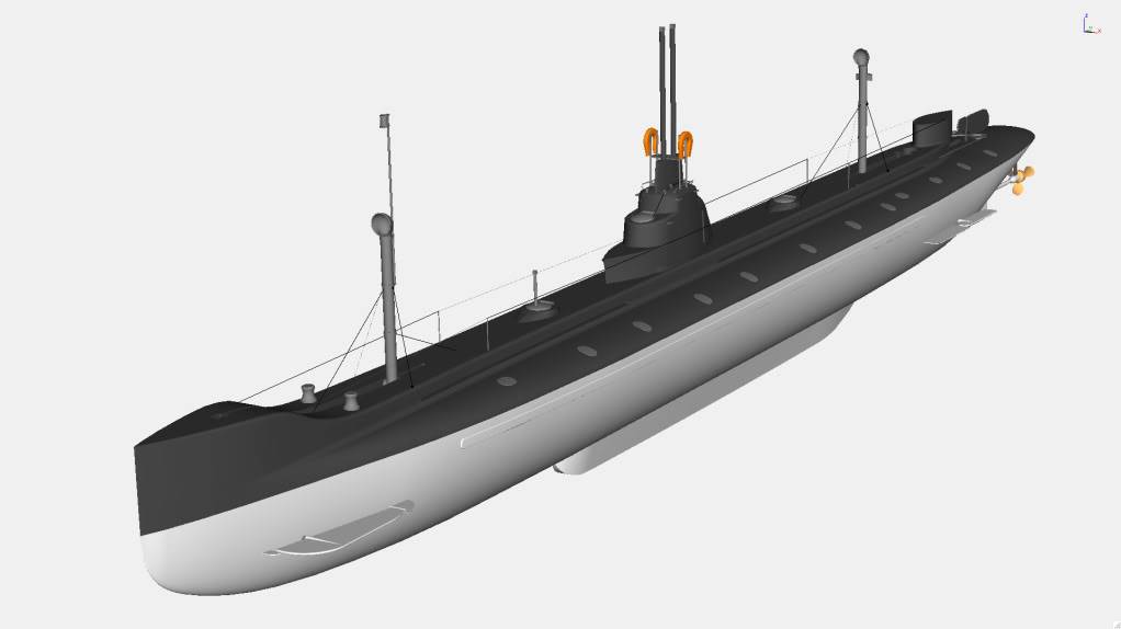
I then found a picture of a scale model on the internet. I imported the picture into a drawing program and drew horizontal and vertical lines at key points on the picture - locations of screw, rudder, stern planes, taper sections, sail (fin), and bow. Then I printed the picture on my ink-jet printer.
The next step was to measure the lengths from the stern and radii from the center line. I measured in millimeters and entered all the data into a spreadsheet (I use Microsoft Excel, but any spreadsheet will do). Knowing the dimensions of the model and the dimensions of the full-sized submarine (length and beam), I was able to scale my measurements to the size I wanted. After scaling, I converted measurements to fractional inches because my CNC machine is calibrated in English units (if I can figure out how to switch it to metric, I will - English units are a pain to use).
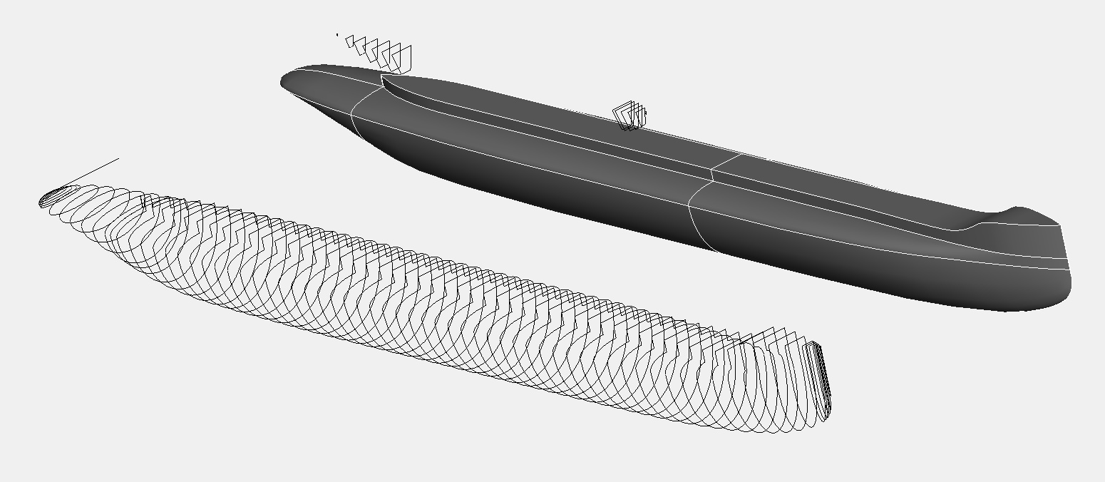
With my dimensions entered into Excel, I used the modeling capabilities of the program to create equations for the curved sections of the hull. I used the equations to generate X & Z coordinates which I then converted to G-Code for my mill and ran the program. I am still in the initial process of this design, and have several more steps to complete.
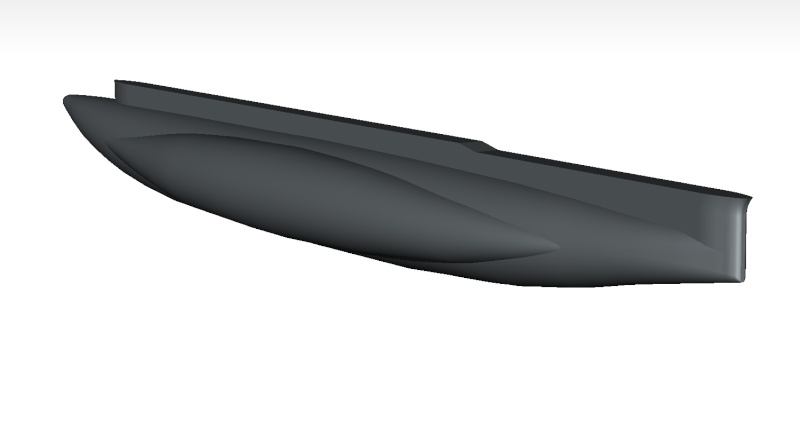
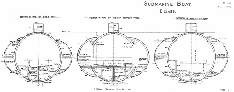
This is going to be a modular build, since the boat I'm modeling was an SSBN with a flat missile deck mounted above the cylindrical hull. This makes the radii of the top and bottom of the hull (in the center and forward sections) different. If I mill the smaller radius section first, then prep and attach another piece of wood to the "top" of the cylinder, I can turn the larger radius section without touching the smaller section.
I suppose I could do a variable radius turning, but I'm still learning my machine and different techniques. Even if I could do that, I'd still have to make the sail, rudder, diving planes, and screw separately, so for this go around I'll just do my modeling in Excel.
Gary





» RC Drift Gyro for pitch control
» WW2 mini sub build
» sonar data link
» Robbe Seawolf V2
» ExpressLRS - 868/915 Mhz equipment
» Flight controllers as sub levelers
» 868/915 Mhz as a viable frequency for submarines.
» Microgyro pitch controller corrosion