Who is online?
In total there are 41 users online :: 0 Registered, 0 Hidden and 41 Guests
None
Most users ever online was 180 on Tue Nov 05, 2019 6:03 am
Latest topics
Search
Most Viewed Topics
Statistics
Our users have posted a total of 12534 messages in 1992 subjects
We have 1021 registered users
The newest registered user is Mike Echo
+9
tsenecal
timgarrod
Tom(ADMIN)
nigele(ADMIN)2
garyalan59
Dr.Schmidt
gantu
david f
profesorul
13 posters
What 3D PROGRAM (S) do YOU use/ How You use it/ What can be done with it?

Tom(ADMIN)- AMS Forum Owner
- Posts : 3026
Join date : 2010-11-05
Age : 64
Location : Nevada, USA
And I haven't a clue what you guys are on about...CAD? CAM? Not a clue...I like my pencil and paper.

profesorul- Guest
- Posts : 386
Join date : 2011-07-03
Age : 60
Location : Bucuresti, ROMANIA
Are ALWAYS reliable huh.

david f- AMS Treasurer
- Posts : 2412
Join date : 2010-11-10
Age : 74
Location : Cumbria
No I don't use anything much like that either. I scan drawings in to a very old version of Paint Shop Pro. This lets me get dimensions off it more easily. Framesizes etc. I then put on a spreadsheet. These then get translated through to wood and clay.
The problem, I suspect is our "build rate". If you are only building a submarine every 2 or 3 years then any investment in time or money in CAD/CAM software is not really justified. If we were manufacturing one every month it would be different. Learn to use a CAD/CAM programme and by the time you get to use it again, you have forgotten the commands, perhaps.
I suppose the time is not far off that we do input everything to CAD/CAM and then send it off to get it 3D printed. We are not there yet not least because you need a plastic that is as tough and repairable as fibreglass, I would say.
David

Tom(ADMIN)- AMS Forum Owner
- Posts : 3026
Join date : 2010-11-05
Age : 64
Location : Nevada, USA
You have a very good point there, David...I too use Paint for anything I need to scan and modify, I find it very simple and easy to use, it does all I need it to do.
I have the greatest respect for those of us, like Marius, who can use and understand these new methods like CAD/CAM, 3D printing, etc. I did take a look at CAD/CAM once, and it frightened the life out of me...I didn't know where to start with it.
I guess us 'oldies' tend to stick to with what we know and understand...you can't really go wrong with a pencil, a ruler, and a sheet of paper. And yes, I still prefer feet and inches over this new fangled metric stuff!
Richard

profesorul- Guest
- Posts : 386
Join date : 2011-07-03
Age : 60
Location : Bucuresti, ROMANIA
Perfectly true DAVID.david f wrote:No I don't use anything much like that either. I scan drawings in to a very old version of Paint Shop Pro. This lets me get dimensions off it more easily. Framesizes etc. I then put on a spreadsheet. These then get translated through to wood and clay.
David
- Can You tell me what version of PAINT SHOP Pro do You use....on what version on Windows (XP ; W7 32/64Bit)? ;
- Can You guide me a litle how can I do it exactly? ;
- and WHAT TYPE of Files can be imported on Paint Shop?...becouse those drowings are most of the time pictures ;
THANK YOU

timgarrod- AMS Website Webmaster
- Posts : 261
Join date : 2013-04-23
Age : 44
i use blender, there is a undo ctrl+z, there a great video series on youtube that i used. not sure if any good for cad work as more 3d models though but I haven't played with it too much
Last edited by timgarrod on Wed Oct 30, 2013 10:57 am; edited 1 time in total (Reason for editing : spelling)

profesorul- Guest
- Posts : 386
Join date : 2011-07-03
Age : 60
Location : Bucuresti, ROMANIA
HI ,
@timgarrod ,
Blender and I think it is a good program for what we need .
But English is not my native language therefore is difficult to understand tehnical terms.
Google translate dossen't make much ;
Can You make a short list of USUAL COMANDS for?.
THANK YOU MARIUS
@timgarrod ,
Blender and I think it is a good program for what we need .
But English is not my native language therefore is difficult to understand tehnical terms.
Google translate dossen't make much ;
Can You make a short list of USUAL COMANDS for?.
THANK YOU MARIUS

timgarrod- AMS Website Webmaster
- Posts : 261
Join date : 2013-04-23
Age : 44
Hi Marcus,
no problem, I get all the short cut I know and will post later
Tim
no problem, I get all the short cut I know and will post later
Tim

timgarrod- AMS Website Webmaster
- Posts : 261
Join date : 2013-04-23
Age : 44
Hi again, just found this online.
easier than having to type up
http://www.keyxl.com/aaac91e/403/Blender-keyboard-shortcuts.htm
easier than having to type up
http://www.keyxl.com/aaac91e/403/Blender-keyboard-shortcuts.htm

profesorul- Guest
- Posts : 386
Join date : 2011-07-03
Age : 60
Location : Bucuresti, ROMANIA
HI ,@timgarrod
THANK YOU so Much.
These is what I'm looking for.
MARIUS
THANK YOU so Much.
These is what I'm looking for.
MARIUS

tsenecal- Guest
- Posts : 322
Join date : 2015-04-01
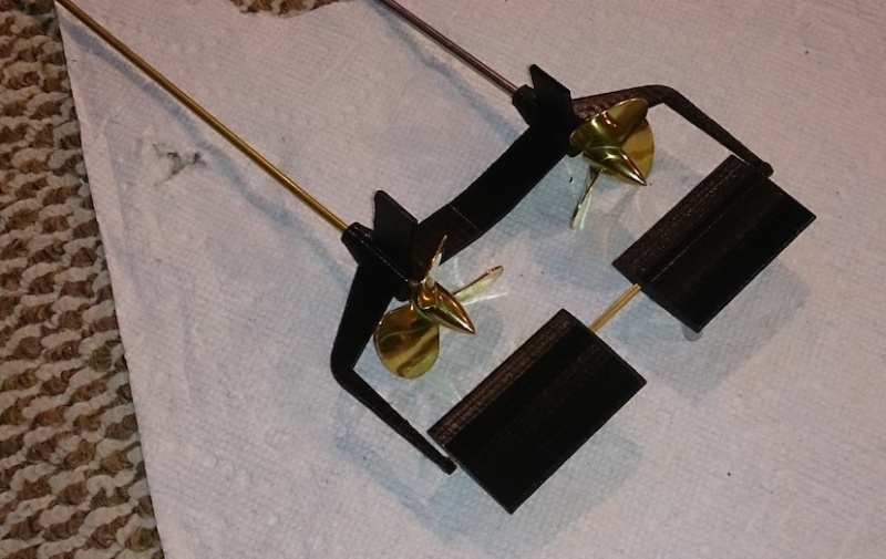
I have just recently purchased a 3d printer, and use google sketchup for what i have built so far... these are parts for a 1:32 scale type VII u-boat i am building..
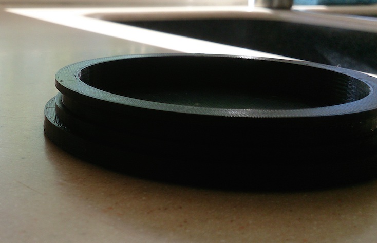
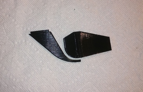
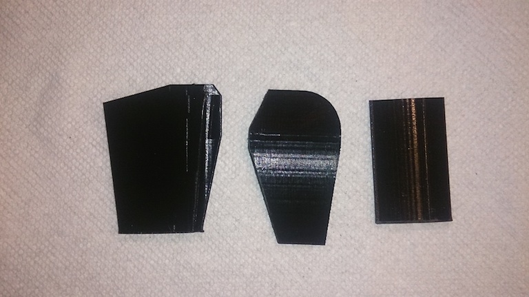
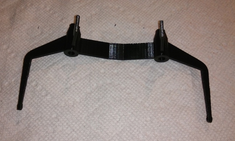


david f- AMS Treasurer
- Posts : 2412
Join date : 2010-11-10
Age : 74
Location : Cumbria
That looks good.
It is interesting to see the way that the technology is developing.
Would you say that it is OK for one-offs or more suitable for repeats? (I am thinking about the time to set it up etc.)
The surface finish is very good but not (and presumably can never be) mirror-smooth? Is it easy to finish off? Would things like WTC end caps need an additional machining step?
Many thanks and more please!
David

tsenecal- Guest
- Posts : 322
Join date : 2015-04-01
David,
things like internal trays for WTCs and endcaps, as long as they are clean enough to fit parts, need no additional cleanup, the endcap you see in the photos was dimensionally correct as soon as it came off the printer. It worked as an endcap, ie, the smallest thickness o-ring i had for that diameter gave me a water-tight seal with that endcap. any additional "things", such as blocks for mounting tech-racks, or holes for pushrods and motor shafts and motor mounting bolts can all be designed into the part, prior to it being printed, so "structural" parts as i call them, would be ready to use right off the printer.
things like the diving planes, rudder, and a-frame are not a good enough finish to install immediately. the filament i use can be sanded rather easily, and a small amount of putty, or filler type primer with some 200 grit sand paper will make the parts ready for installation, or in my case, i will probably use them as masters for rubber molds.
its difficult to tell from the photos, but all the diving planes and rudders are made with 2mm x 2mm square holes in them, which, after a small amount of cleanup, are ready for brass tubing to be installed for the proper hinge for each part.
the a-frame is not quite stiff enough to be used directly out of the printer, but if i were to make it thicker, it probably would work.
the question about on-off design is simply the classic "cost-benefit" ratio. would it be faster/easier to build the one-off by hand, or design and print it? for me, i haven't yet asked that question. I rationalize the time spent drawing a rather simple object as "learning".
as to the time involved, sketchup took me a week to get comfortable with, but then, most of my living has been spent using tools like adobe illustrator and adobe photoshop, so cad/cam types of software come easy to me. obviously, the more complicated the part, the more time it takes to draw it, but all the items pictured took between 30 minutes (end cap) and 3 hours (a-frame) to draw, and then the file is put on an SD card, the SD card is put in the printer, and then i let it run while i sleep. i can get a status after it is finished, to find out how long it took, and none of the "files" you see took more than 4 hours to print. the rear diving planes each took 30 minutes.
things like the endcap and a-frame benefit most from the use of 3d cad software. i only had to draw one side of the a-frame, then duplicated and mirrored that one side to create the second side in about 30 seconds. the endcap will have about 10 different derivatives, with different holes and mounting points (two motors, one motor, 3 pushrods, two pushrods, 1 pushrod, etc.) I am even investigating what it would take to design a fixture for a cup seal directly into the endcap, so that propshafts and pushrods would not require any additional hardware (except the seal) to work.
one item i am hoping to try (both to draw and to print) is a giant 5" 5 bladed prop... a replacement for the propeller on my Alvin submersible. I dont NEED one, but i want to see if i can draw and print one. if i am successful at that, the 3d printer will actually be "better" than the mill i own.
a test fitting of parts on the a-frame and rear planes:


Proflooney- Posts : 23
Join date : 2016-10-29
I use Solidworks been using it for aircraft design for years. since I am about to start my first sub/boat design I will do a whip in this forum and will be able to show the nice features of solidworks as I go. solidworks made designing planes so easy it was silly and should be the same with subs and boats. now for enlarging isf I have soso quality I like to use corel draw as when I enlarge my drawings the lines dont get thicker like most programs do to them. usually I will do a trace in corel draw once i enlarge my drawing sheet then sav e my traced info to a dxf file for solidworks. however you can bring images in solidworks and enlarge them without too much problems with lines thickening it depends on how much you are enlarging by

CADArtist1965- Posts : 1
Join date : 2020-01-23
Location : Chichester West Sussex
I have been building a 3D model of an Oberon Class submarine on and off for around 6 months or so. before I started I did a lot
of research into the type, spending a lot of time amassing as many images and photographs to help me accurately depict the class of submarine.
My initial idea was to design a printable model, however because I don't have the money to buy a high quality large volume 3D printer, I had a look
at getting my prints done through sculpteo. So far I have either found that my parts were too complex, too large making it ridiculously expensive or
not printable. It seems that when it comes to 3D printing there are so many aspects you need to consider, for example mesh-size how many triangles, wall thickness,
complex curved surfaces, nevermind about what material, print-speed or temperature and layer height you need to set.
I use Solidworks because it is an excellent CAD design software platform for many different applications.
learning to be able to import an image file, size and
scale it then build an accurate 3D model from it, give you a great sense of achievement.
I just wish I had the money and space for a nice workshop.
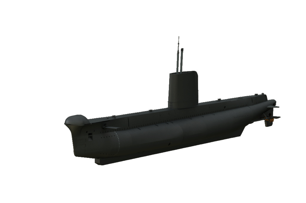
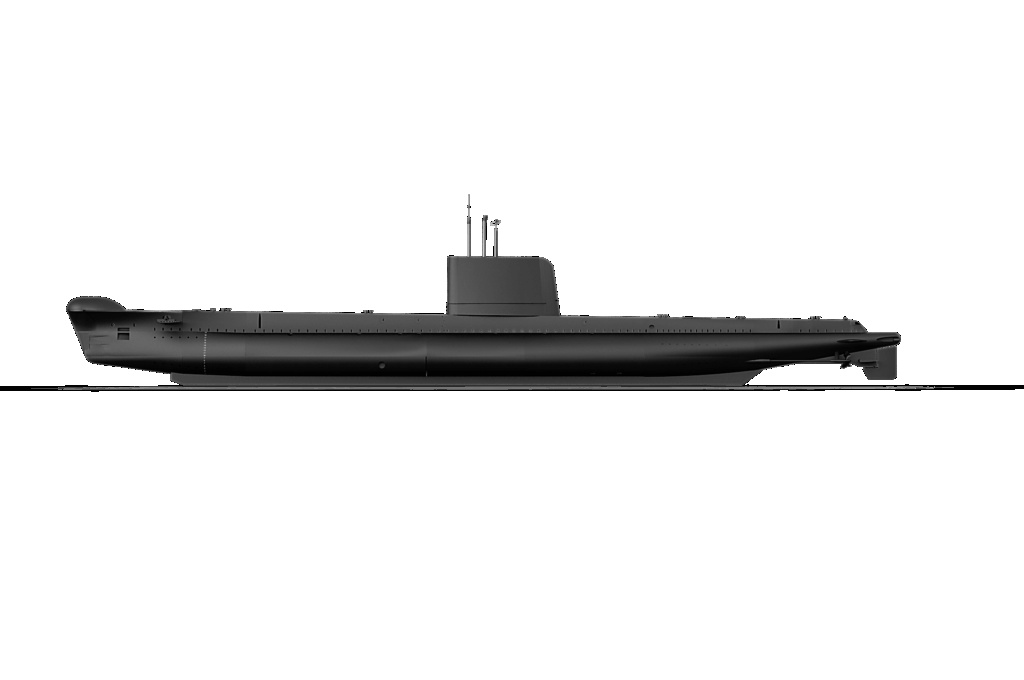


david f- AMS Treasurer
- Posts : 2412
Join date : 2010-11-10
Age : 74
Location : Cumbria
Very nice!
A nice looking sub the O class.
I have been using Autodesk Fusion 360 for a year or so but only to make small parts for my subs. Tim Garrod recommended Autodesk to me not least because you can get a free version for Students and Hobbyists. (I hope it still is free but I couldn't check this without making another application.)
3D printing has changed the way I make things. I no longer worry about complex curves and I like the way I can just run off a handful of parts as easily as one.
David
Last edited by david f on Tue Jan 28, 2020 8:34 am; edited 1 time in total

salmon- AMS Forum Owner
- Posts : 312
Join date : 2011-09-02
Age : 64
Location : Las Vegas, Nevada - USA
I also use Fusion 360. David made a statement that I want to emphasize, you do not have to follow traditional building ideas. On a piston system I am working on, the water inlet and outlet could have been any shape I wanted. for this portion round did work, but I could have built square piping and built it into the frame if I wanted. You definitely can let your imagination run free.
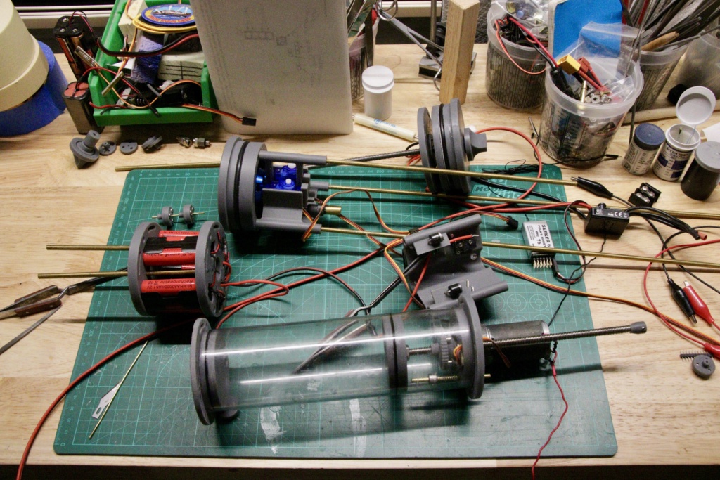


ccclarke- Posts : 14
Join date : 2021-02-20
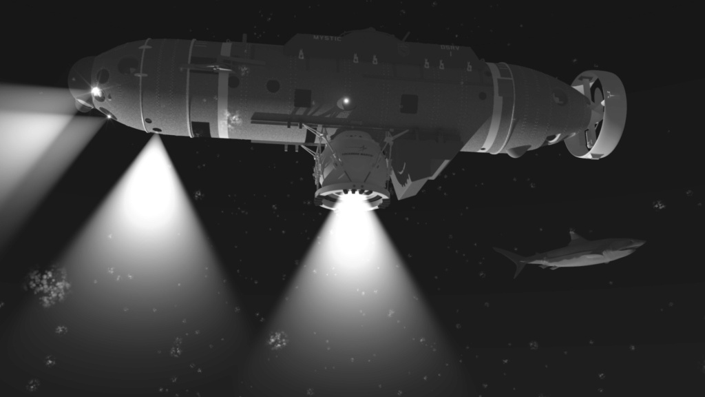
I use Lightwave3D professionally to create photo-realistic models for animation and briefing presentation packages. Lightwave models can be saved in STL format for ease of 3D printing once the mesh is "watertight".
Lightwave3D has been used in television and movies for decades, so it's an ideal application for photo-realistic visualization and animation to examine a model prior to printing, instead of most CAD programs which render cartoonish images. With a powerful yet easy-to-learn modeling UI, being able to create exceptionally detailed models in both hard surface and organic (sub-divisional) styles for 3D printing is an added plus.
CC


david f likes this post

david f- AMS Treasurer
- Posts : 2412
Join date : 2010-11-10
Age : 74
Location : Cumbria
A very interesting thread on the SubCommittee Forum showing some of the detail behind 3D design pitfalls:
https://subcommittee.com/forum/showthread.php?38542-German-3D-printed-RC-submarine
https://subcommittee.com/forum/showthread.php?38542-German-3D-printed-RC-submarine

ccclarke- Posts : 14
Join date : 2021-02-20
C'est moi!
On that forum, my username is X Bubblehead. It's the only forum where I've departed from using my real name.
If a comprehensive tutorial is created, I'll post it here as well, since I believe information that teaches others is more useful when shared, not hoarded.
This is why I requested any of my efforts be kept in an open forum; the Subcommittee contains a lot of private sections on the site.
It would not be released right away though. Creating tutorials requires a considerable amount of time to ensure their message is effectively and accurately communicated to the intended audience.
CCC
david f likes this post

ccclarke- Posts : 14
Join date : 2021-02-20
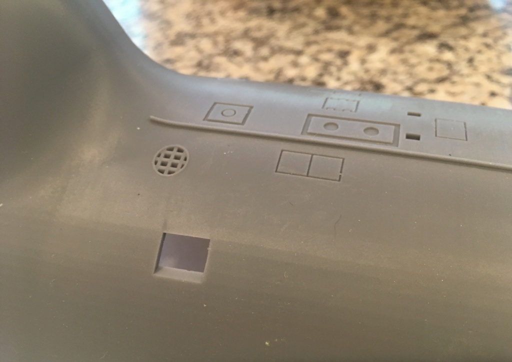
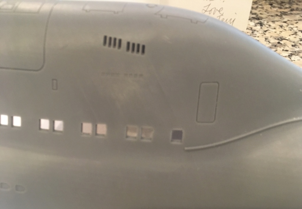
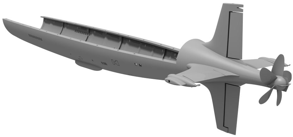
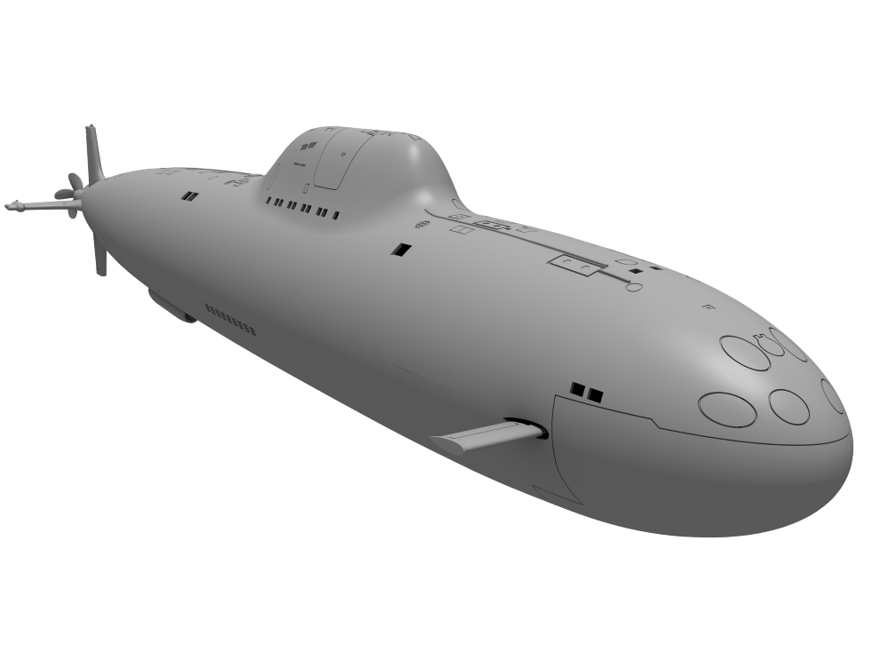
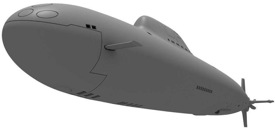
This Russian Alpha 3D file is for sale @ Nautilus Drydocks. I have re-modeled about 90% of the original files for added interior RC functionality and exterior detail accuracy. The hull is 3D printed using a resin printer. This allows very high detail with layer lines so fine, (50 microns thick) sanding is optional.
The interconnect frames for each section, (there are fourteen) are printed on an FDM printer. ABS filament is recommended for heat resistance.
While using Lightwave 3D to revise this model, I've taken up Fusion 360 and am getting more familiar with it with practice. It is a parametric modeling program where Lightwave is not. This powerful feature allows you to go back in the construction timeline to tweak the model by editing the dimension or position previously performed and the change ripples through the rest of the model's build progress.
Saving time is a huge consideration when 3D modeling and being able to make changes (non-destructively) without having to manipulate the mesh directly checks that box nicely.
I've attached a couple of shots of the 3D model and a resin print of a hull section.
CC


david f likes this post



» RC Drift Gyro for pitch control
» WW2 mini sub build
» sonar data link
» Robbe Seawolf V2
» ExpressLRS - 868/915 Mhz equipment
» Flight controllers as sub levelers
» 868/915 Mhz as a viable frequency for submarines.
» Microgyro pitch controller corrosion